
Sample chamber

Active Publication Date: 2018-03-27
IBIDI
View PDF17 Cites 2 Cited by
  • Summary
  • Abstract
  • Description
  • Claims
  • Application Information

AI Technical Summary

Benefits of technology

This patent aims to provide a sample chamber with a protected electrical contact. The sample chamber comprises an electrical contact electrode, a conductor path, and a sample chamber holder to establish an electrical connection. The technical effect of this invention is to protect the contact electrodes and conductor paths from damage.

Problems solved by technology

Especially in systems where the conductors and electrodes are formed of very thin layers or are arranged on thin carrier plates it may occur that the contact points or the conductors connecting same to the electrodes in the MEA system are easily damaged.

Method used


Image

  • Sample chamber
  • Sample chamber
  • Sample chamber

Examples


Embodiment Construction

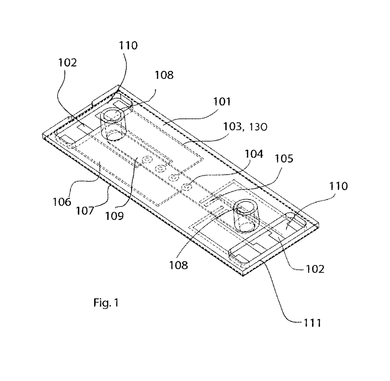
[0064]FIG. 1 shows an example of a sample chamber 101, comprising contact electrodes 102, conductor elements and excitation and measuring electrodes 104, 105. In this embodiment the conductor elements are designed as conductor paths 103. Alternatively, semiconductor elements 130 may be provided. The sample chamber is, in this embodiment, rectangular. The planar part of the sample chamber may have a size, for example, of 75 mm ×25 mm ×2 mm. Four contact electrodes 102 are respectively located at the bottom of each one of the two blind holes 110. The two blind holes 110 are arranged on the opposite ends of the longitudinal axis of the sample chamber 101. One contact electrode 102 is connected by one conductor path 103 to one measuring electrode 104 or excitation electrode 105. The excitation electrodes 105 and the measuring electrodes 104, respectively, are arranged in a sample reservoir which is designed as a channel-shaped hollow space 109. Parts of the cover plate 106 are designed ...


PUM


Abstract

The invention relates to a sample chamber for testing samples, comprising a bottom plate and a cover plate connected thereto, a sample reservoir for receiving a liquid and / or a sample to be tested, and a contact electrode which is arranged entirely in the bottom plate, in the cover plate or between the bottom plate and the cover plate and which is electrically conductively connected to a conductor element or semiconductor element disposed in and / or on the sample chamber, wherein the bottom plate and / or the cover plate are designed in such a way that an electrical contact with the contact electrode can be established from the outside in such a way that an electrically conductive connection to the conductor element or to the semiconductor element can be established from the outside through the bottom plate or through the cover plate via the contact electrode.

Description

FIELD OF THE INVENTION[0001]The invention relates to a sample chamber for testing especially chemical and biological samples, to a sample chamber holder and to a system comprising a sample chamber and a sample chamber holder.BACKGROUND OF THE INVENTION[0002]Especially in the fields of cytobiology and medicine sample chambers having integrated conductor paths and electrodes are used for the testing of cells, specifically living cells. Among others, the alternating current resistance of an electrode covered with cells is measured as a function of time. Such sample chambers are also referred to as MEA (Multi Electrode Array) systems. Also, it is possible to use MEA systems for chemical and pharmacological applications.[0003]A MEA system is known, for example, from U.S. Pat. No. 5,187,096 which comprises several receiving wells for receiving the cells to be tested, in which electrodes are arranged for measuring the impedance of cell cultures. The electrodes are connected to contact stri...

Claims


Application Information

Patent Timeline
IPC IPC(8): B01L1/00B01L3/00G01N33/483
CPCG01N33/4836B01L3/502715B01L2300/0829B01L2200/10B01L2300/0645B01L2200/027
Inventor ZANTL, ROMANKAHL, VALENTIN
Owner IBIDI
Features
  • Generate Ideas
  • Intellectual Property
  • Life Sciences
  • Materials
  • Tech Scout
  • Unparalleled Data Quality
  • Higher Quality Content
  • 60% Fewer Hallucinations
Learn More