
Touch panel and display apparatus including the same

a display apparatus and touch electrode technology, applied in the field of touch electrodes and display apparatuses, can solve problems such as malfunction of display electrodes with capacitive touch panels, and achieve the effects of improving rc delay, reducing resistance of touch electrodes, and improving display apparatus

Active Publication Date: 2018-03-27
SAMSUNG DISPLAY CO LTD
View PDF54 Cites 14 Cited by
  • Summary
  • Abstract
  • Description
  • Claims
  • Application Information

AI Technical Summary

Benefits of technology

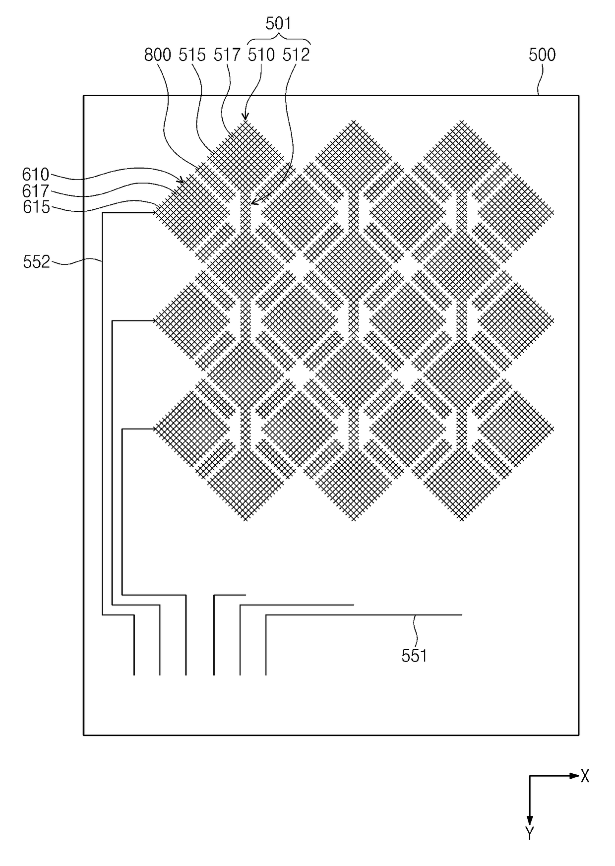
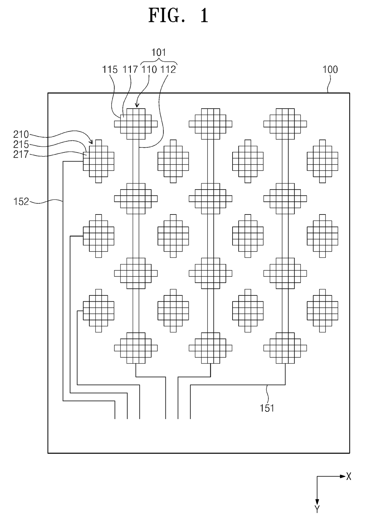
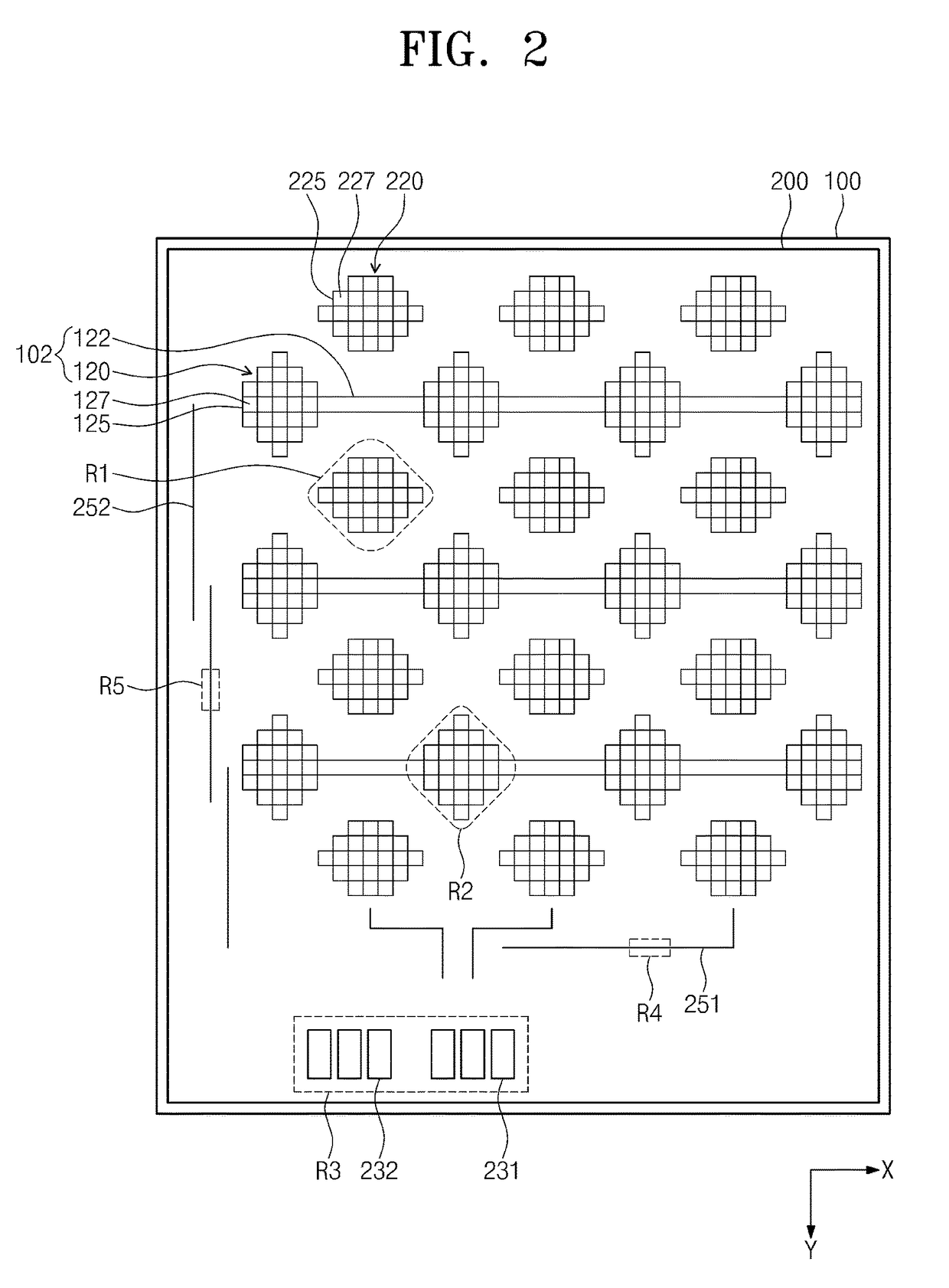
[0010]Exemplary embodiments provide a touch panel in which an auxiliary mesh electrode is provided to reduce resistance of a touch electrode and thus improve RC delay and a display apparatus including the same.
[0011]Exemplary embodiments also provide a touch panel that is capable of securing uniform visibility over an entire region and a display apparatus including the same.

Problems solved by technology

However, a display panel with a capacitive touch panel may malfunction because the capacitive touch panel has a considerable RC delay due to parasitic capacitance existing between a touch electrode and another component (e.g., a cathode electrode).

Method used


Image

  • Touch panel and display apparatus including the same
  • Touch panel and display apparatus including the same
  • Touch panel and display apparatus including the same

Examples


Embodiment Construction

[0057]In the following description, for the purposes of explanation, numerous specific details are set forth in order to provide a thorough understanding of various exemplary embodiments. It is apparent, however, that various exemplary embodiments may be practiced without these specific details or with one or more equivalent arrangements. In other instances, well-known structures and devices are shown in block diagram form in order to avoid unnecessarily obscuring various exemplary embodiments.

[0058]In the accompanying figures, the size and relative sizes of layers, films, panels, regions, etc., may be exaggerated for clarity and descriptive purposes. Also, like reference numerals denote like elements.

[0059]When an element or layer is referred to as being “on,”“connected to,” or “coupled to” another element or layer, it may be directly on, connected to, or coupled to the other element or layer or intervening elements or layers may be present. When, however, an element or layer is re...


PUM


Abstract

A touch panel including a substrate, first touch electrodes, each of the first touch electrodes including first mesh patterns disposed on the substrate, an insulation layer disposed on the first touch electrodes, second touch electrodes, each of the second touch electrodes including second mesh patterns disposed on the insulation layer, first auxiliary mesh electrodes disposed on the substrate, the first auxiliary mesh electrodes being electrically connected to at least a portion of the corresponding second mesh patterns, and second auxiliary mesh electrodes disposed on the insulation layer, the second auxiliary mesh electrodes being electrically connected to at least a portion of the corresponding first me patterns.

Description

CROSS-REFERENCE TO RELATED APPLICATIONS[0001]This application claims priority from and the benefit of Korean Patent Application Nos. 10-2014-0105280, filed on Aug. 13, 2014, 10-2014-0113367, filed on Aug. 28, 2014, and 10-2015-0021837, filed on Feb. 12, 2015, which are hereby incorporated by reference for all purposes as if fully set forth herein.BACKGROUND[0002]Field[0003]Exemplary embodiments relate to a touch panel and a display apparatus including the same.[0004]Discussion of the Background[0005]Touch panels are input devices for inputting a predetermined command when touched by a user's own hand or an object.[0006]Because touch panels can substitute for separate input devices such as a keyboard, a mouse, and the like, they are being used more often in mobile devices.[0007]A touch panel may include many types, such as a resistive overlay touch panel, a photosensitive touch panel, and a capacitive touch panel. Among these touch panel types, the capacitive touch panel is widely us...

Claims


Application Information

Patent Timeline
Patent Type & Authority Patents(United States)
IPC IPC(8): G06F3/047G09G5/00G06F3/044
CPCG06F3/047G06F3/044G09G5/003G09G2300/0426G06F2203/04111G06F2203/04112G06F3/0443
Inventor NA, HYUNJAEJUN, SANGHYUNKO, GWANG-BUMLEE, JOOHYUNGLEE, JIGONGJANG, HYOUNGWOOKAHN, SOONSUNG
Owner SAMSUNG DISPLAY CO LTD
Learn More