Bistable relay and bistable actuator

a bistable actuator and relay technology, applied in the direction of magnets, magnetic circuit shapes/forms/construction, magnetic bodies, etc., can solve the problems of large volume of bistable relays, static power consumption of monostable relays, and difficult to reduce, etc., to achieve good magnetic latching efficiency, small volume, and high electromagnetic conversion efficiency

Active Publication Date: 2018-04-03
LIANG
View PDF29 Cites 6 Cited by
  • Summary
  • Abstract
  • Description
  • Claims
  • Application Information

AI Technical Summary

Benefits of technology

[0006]The invention is directed to a bistable relay and a bistable actuator, the bistable actuator has good magnetic latching efficiency, high electromagnetic conversion efficiency and a small volume. The bistable relay derived from the bistable actuator not only has the characteristics of the bistable actuator, but also improves reliability of a contact system of the bistable relay.
[0011]In an embodiment of the invention, the electromagnet further includes at least one second magnetic guiding component, which is connected to the first magnetic guiding component, and is configured to increase electromagnetic efficiency of the electromagnet, so as to decrease an electric energy transition driving force required by the electromagnet for driving the magnetic latching mechanism.
[0022]According to the above descriptions, the bistable actuator of the invention is adapted to operate between the first stable state and the second stable state, where the columnar hollow magnetic conductor and the pillar-shaped permanent magnet maintain a gap therebetween, and the gap is varied along with different positions of the inner surface of the columnar hollow magnetic conductor, and is configured to guide the pillar-shaped permanent magnet to rotate to a stable position. Moreover, the first portion and the second portion of the columnar hollow magnetic conductor of the magnetic latching mechanism are respectively spaced by a first distance and a second distance from the pillar-shaped permanent magnet of the magnetic latching mechanism, and the first distance is the shortest distance between the first portion of the columnar hollow magnetic conductor and the pillar-shaped permanent magnet, and the second distance is the shortest distance between the second portion of the columnar hollow magnetic conductor and the pillar-shaped permanent magnet. The electromagnet may drive the pillar-shaped permanent magnet to rotate along the axial direction to make the magnetic latching mechanism to switch the stable state. During the process that the magnetic latching mechanism switches the stable state, the rotation shaft rotates synchronously along with the magnetic latching mechanism. In this way, the bistable actuator of the invention may have good magnetic latching efficiency and high electromagnetic conversion efficiency through an attraction force between the columnar hollow magnetic conductor and the pillar-shaped permanent magnet, so as to strengthen stableness of the bistable relay in the stable state. Moreover, when the bistable actuator is applied to the bistable relay, during the process that the magnetic latching mechanism switches the stable state, the rotation shaft rotates synchronously along with the magnetic latching mechanism to drive the impact system of the bistable relay to move relative to the contact system, so as to contact or disconnect the contact points. In this way, the bistable relay of the invention improves contact reliability of the contact system thereof.

Problems solved by technology

Therefore, the monostable relay still has static power consumption even if the state thereof is not changed, and a total volume thereof is relatively large.
Although such type of the bistable relay has a power saving effect compared to the monostable relay, a mechanism of the bistable relay is relatively complicated, and due to poor electromagnetic conversion efficiency, the volume of the bistable relay is large and is not easy to be decreased, so that application thereof is limited.

Method used


Image

  • Bistable relay and bistable actuator
  • Bistable relay and bistable actuator
  • Bistable relay and bistable actuator

Examples


Embodiment Construction

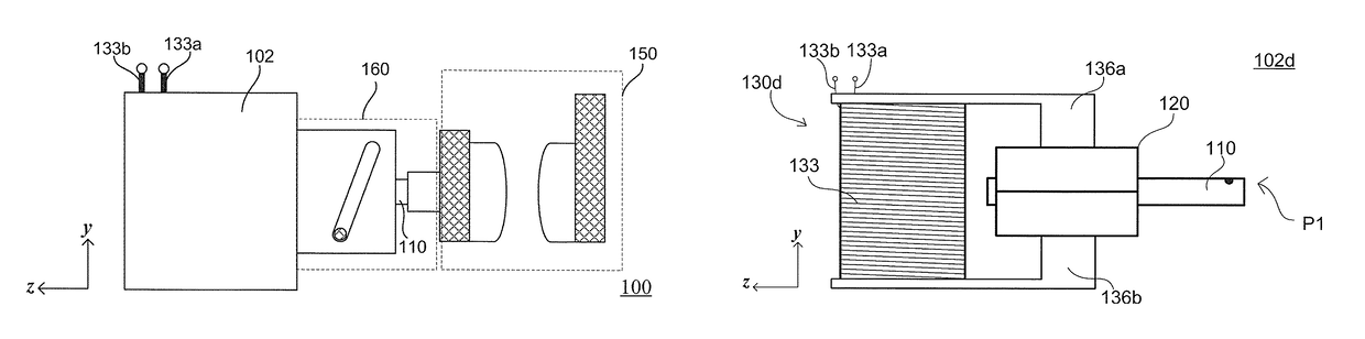
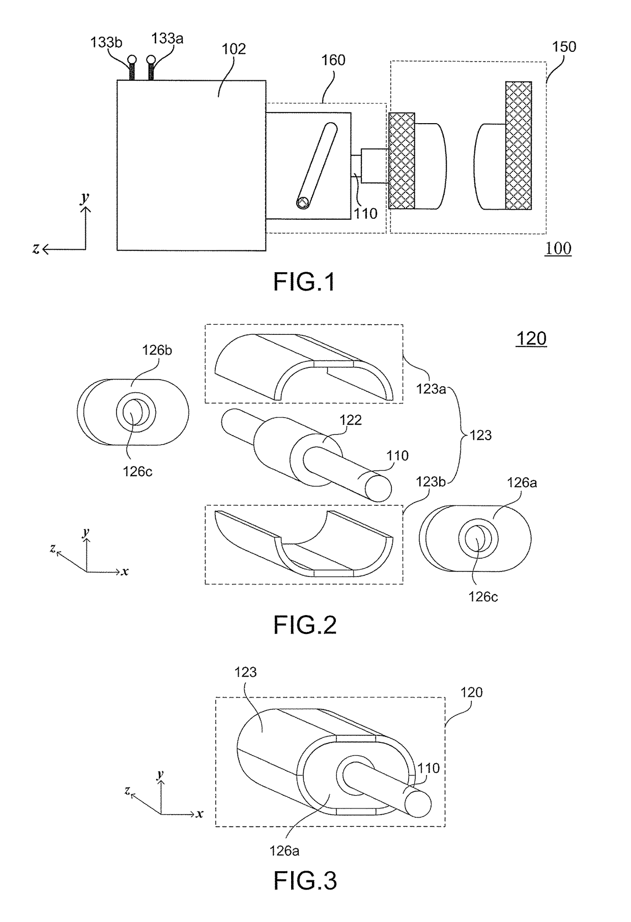
[0057]FIG. 1 is a schematic diagram of a bistable relay according to an embodiment of the invention. Referring to FIG. 1, in the present embodiment, the bistable relay 100 includes a bistable actuator 102, an impact system 160 and a contact system 150, where the bistable actuator 102 has a rotation shaft 110 and coil terminals 133a and 133b, and a detailed structure thereof (including a magnetic latching mechanism 120 and an electromagnet 130) is shown in subsequent figures. The bistable relay 100 is configured in a circuit to serve as a switch for closing or opening the circuit. The bistable actuator 102 is adapted to operate between a first stable state and a second stable state (shown in subsequent figures). The rotation shaft 110 is disposed along an axial direction (for example, a z-axis). By introducing currents with different directions to the coil terminals 133a and 133b, the bistable actuator 102 is driven from one stable state to the other stable state. The impact system 1...


PUM

PropertyMeasurementUnit
rotation angleaaaaaaaaaa
magneticaaaaaaaaaa
magnetic fieldsaaaaaaaaaa

Abstract

A bistable relay and a bistable actuator are provided. The bistable actuator includes a magnetic latching mechanism and an electromagnet. The magnetic latching mechanism includes a rotation shaft, a pillar-shaped permanent magnet, a columnar hollow magnetic conductor and two shells, and operates between a first and second stable states. The columnar hollow magnetic conductor surrounds the pillar-shaped permanent magnet wrapping the rotation shaft, and maintains a gap with the pillar-shaped permanent magnet. The electromagnet is connected to the columnar hollow magnetic conductor for driving the pillar-shaped permanent magnet to rotate, so as to switch the magnetic latching mechanism to the stable state. During a process that the magnetic latching mechanism is switched to the stable state, the rotation shaft rotates synchronously along with the magnetic latching mechanism to drive an impact system to move relative to a contact system, so as to contact or disconnect the contact points.

Description

BACKGROUND OF THE INVENTION[0001]Field of the Invention[0002]The invention relates to an actuator, and particularly relates to a bistable relay and a bistable actuator.[0003]Description of Related Art[0004]Relay is an electronic control device generally applied in an automatic control circuit. The relay is switched between two states to contact or disconnect contact points of a contact system, so that the relay is regarded as an “automatic switch”. Therefore, the relay provides functions of automatic adjustment, safety protection, a conversion circuit, etc., in the automatic control circuit.[0005]Types of the relays are diversified, taking an existing monostable relay as an example, in one of the states of the monostable relay, the contact points of the contact system can be directly contacted or disconnected through a metal elastic force without requiring an extra driving power. However, in another state of the monostable relay, an electromagnetic coil of the monostable relay has t...

Claims


Application Information

Patent Timeline
Patent Type & Authority Patents(United States)
IPC IPC(8): H01H51/22H02K7/06H02K1/14H02K26/00H01F7/122H01H50/64H01H50/22H01F7/14H01H50/44
CPCH01H50/22H01F7/122H01F7/14H01H50/44H01H50/643H01H51/2263H02K1/143H02K7/06H02K26/00H01H50/645H02K2201/03H01H2205/002
Inventor LIANG
Owner LIANG
Why Eureka
Try Eureka