Automatic impedance matching for a radiofrequency reception chain

a radiofrequency reception chain and automatic technology, applied in the direction of transmission, line impedence variation compensation, power management, etc., can solve the problems of low reflected power, degraded performance levels, and loss of mismatch losses

Inactive Publication Date: 2018-04-03
COMMISSARIAT A LENERGIE ATOMIQUE ET AUX ENERGIES ALTERNATIVES
View PDF10 Cites 5 Cited by
  • Summary
  • Abstract
  • Description
  • Claims
  • Application Information

AI Technical Summary

Benefits of technology

[0016]According to the invention, this aim is achieved by tuning the matching network according to the gain of the reception chain and the noise level—expressed, for example, by the signal-to-noise ratio (SNR)—measured at the output of the LNA. More particularly, these two measurements make it possible to determine the antenna impedance and thus to perform impedance matching directly.

Problems solved by technology

These impedance variations may cause losses called mismatch losses: these losses result from the fact that the transmission chain that feeds the antenna, or the reception chain that receives a signal from the antenna, is generally designed to have optimum performance levels when it is loaded (at the output for the transmission chain or at the input for the reception chain) with a quite specific nominal impedance; it has degraded performance levels when it is loaded with an impedance that is different from its nominal value.
This method suffers from two disadvantages: firstly, the reflected power may be low and subject to parasitic interference, because any interference picked up by the antenna comes to distort the measurement owing to the fact that it is added to the reflected power.
This method therefore leads to a new impedance that is not necessarily optimum, because a plurality of pairs of complex impedances correspond to a given power.
The convergence of the iterative optimization algorithm may be very slow.
These techniques operate well in transmission, but applying them to reception chains is much trickier.
Specifically, the power of the signal output by the antenna is very low, and it is difficult to drain off a portion of it in order to take the measurements that make impedance matching possible; in the best case, this requires the use of high-precision detection circuits, which are very complex and expensive.
However, this is not always possible since certain LNAs are designed in such a way as to have an output impedance that is substantially independent of their input impedance: in this case, measurements taken at the output of the amplifier do not allow the antenna impedance to be determined.
This solution is not satisfactory since, in the absence of special precautions, maximizing the output power may result in a very high noise level, which is not acceptable.
These methods proceed by trial and error; they are therefore relatively slow, and the operation of the reception chain is heavily disrupted for the duration of the matching phase.

Method used


Image

  • Automatic impedance matching for a radiofrequency reception chain
  • Automatic impedance matching for a radiofrequency reception chain
  • Automatic impedance matching for a radiofrequency reception chain

Examples


Embodiment Construction

[0030]The term “radiofrequency” is understood to mean any frequency between 3 kHz and 300 GHz.

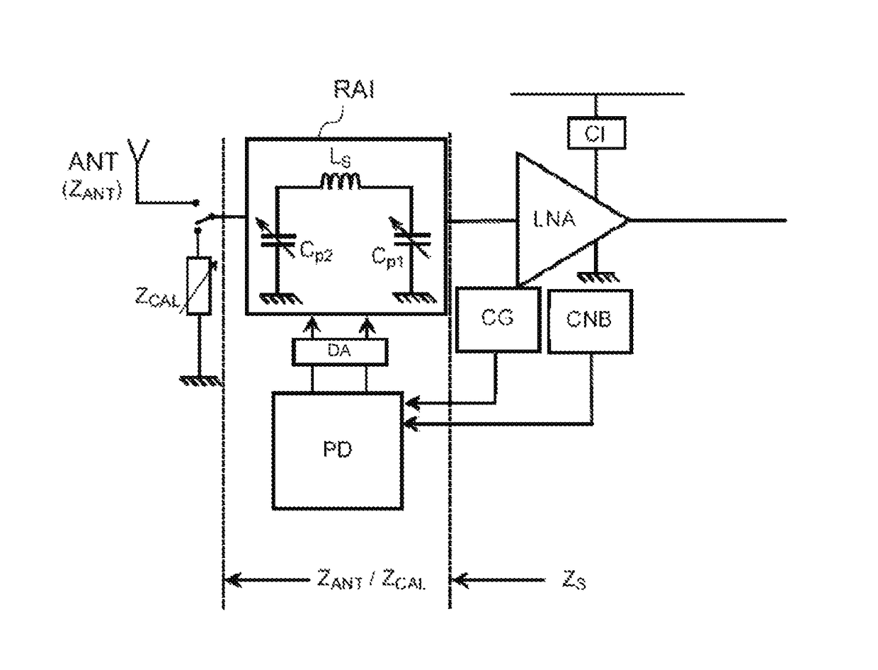
[0031]The term “low-noise amplifier” is understood to mean an amplifier whose input is connected, or intended to be connected, either directly or indirectly, to a receiving antenna.

[0032]The term “reactive element” is understood to mean an electrical component whose impedance has, at at least one frequency in the radiofrequency domain, a reactive (capacitive or inductive) component that is greater than or equal to—and preferably greater, by a factor 10 or more, than—its resistive component.

[0033]Throughout the rest of the text, the signals in the matching network will be considered to have a single frequency f=ω / 2π, thereby allowing a capacitive or inductive element (reactive element) to be characterized by a reactance value. This approximation is generally satisfactory in the radiofrequency domain.

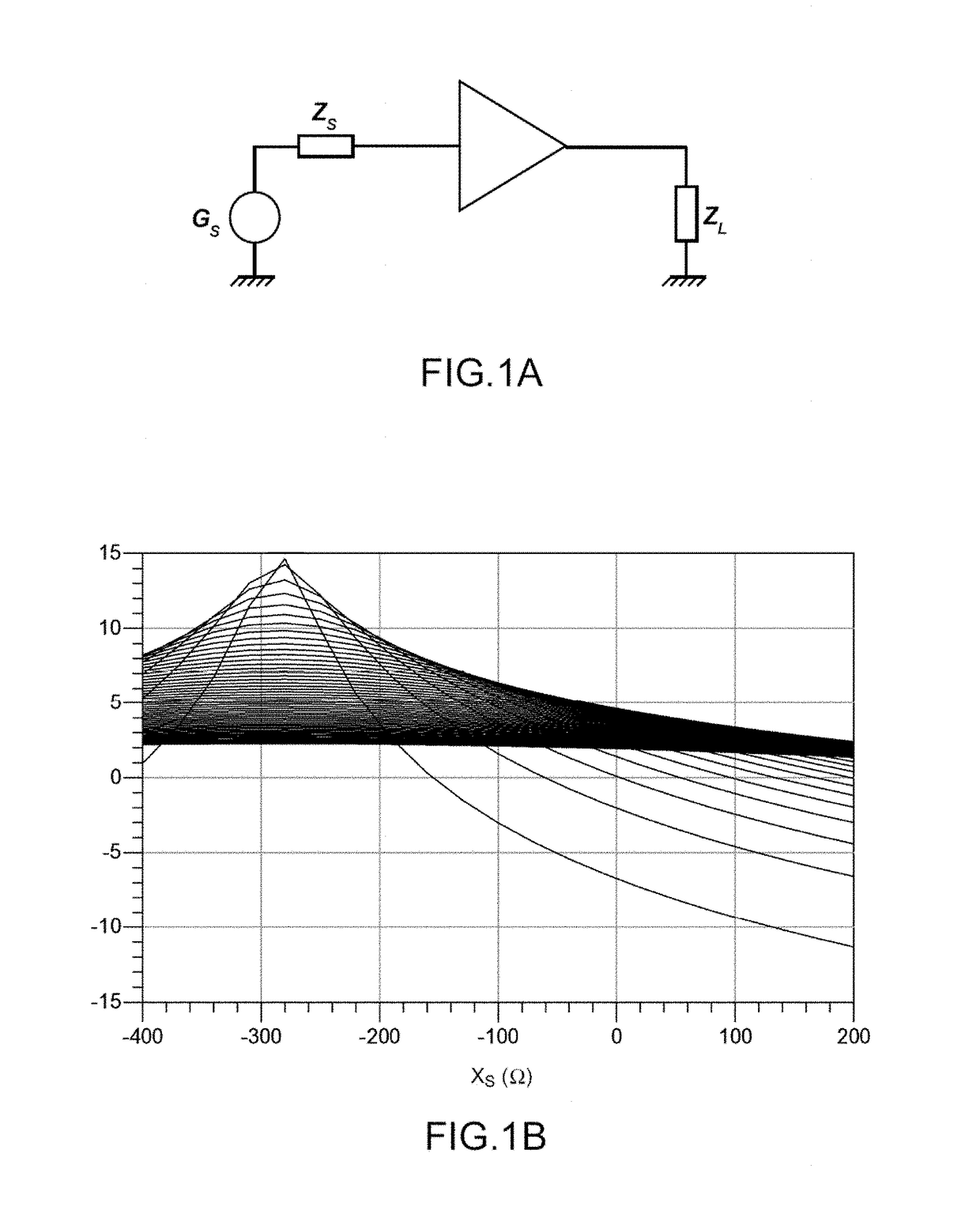
[0034]The term “impedance matching” is understood to mean a condition under which the transfe...


PUM


Abstract

An automatic impedance-matching method for a radiofrequency reception chain, which includes an antenna, an amplifier and a configurable impedance-matching network, arranged between the antenna and an input of the amplifier. The method includes two steps: acquiring measurement of a gain of the reception chain and of a noise level at an output of the amplifier and tuning the impedance-matching network according to the measurements. A radiofrequency reception chain allowing the method to be implemented is also provided.

Description

CROSS-REFERENCE TO RELATED APPLICATION[0001]This application claims priority to foreign French patent application No. FR 1562673, filed on Dec. 17, 2015, the disclosure of which is incorporated by reference in its entirety.FIELD OF THE INVENTION[0002]The invention pertains to an automatic impedance-matching method for a radiofrequency reception chain, and, more specifically, to an automatic antenna matching method. The invention also pertains to a radiofrequency reception chain allowing such a method to be implemented.BACKGROUND[0003]In some radio-frequency information transmission applications, it has been found that the transmission or reception antenna could have an impedance that is highly dependent on external conditions, and notably dependent on the environment in which the antenna is placed.[0004]By way of example, in medical telemetry, there may be cause to introduce the antenna into a probe placed in the human body, and the impedance is then highly dependent on the biologic...

Claims


Application Information

Patent Timeline
Patent Type & Authority Patents(United States)
IPC IPC(8): H04L25/12H03H11/30H04L5/00H04W52/52H03H7/40H04B1/10H04B1/12H04B1/18
CPCH04L25/12H03H7/40H03H11/30H04W52/52H04L5/006H04B1/18H04B1/1027H04B1/123
Inventor DE FOUCAULD, EMERICTARIS, THIERRY
Owner COMMISSARIAT A LENERGIE ATOMIQUE ET AUX ENERGIES ALTERNATIVES
Why Eureka
Try Eureka