
Joining apparatus and method

a technology of joining apparatus and components, applied in metal-working apparatus, metal-working apparatus, manufacturing tools, etc., can solve the problems of increasing demands, reducing ductility, and prone to fracture,

Active Publication Date: 2018-04-10
ATLAS COPCO IAS UK LIMITED
View PDF46 Cites 2 Cited by
  • Summary
  • Abstract
  • Description
  • Claims
  • Application Information

AI Technical Summary

Benefits of technology

The present invention provides an improved joining method and apparatus for producing riveted joints in overlapping workpieces. By applying ultrasonic energy to deform the workpieces and induce an acousto-plastic effect, the method reduces the required compressive force and therefore the mean forming forces for the joint. In addition, the method can be used with either a rivet or a clinching method. The apparatus includes a joining tool and a die, and ultrasonic energy can be applied to at least one of the workpieces or the joining tool to increase ductility of the workpiece.

Problems solved by technology

SPR is faced with increasing challenges in terms of the types of joints that manufacturers would like to produce using the technology.
Rivets can be made harder to withstand the insertion forces required to pierce the high strength metals but they then exhibit lower ductility and may be prone to fracture during the flaring stage of insertion.
Moreover, the thicker and / or higher strength materials generally require increased setting forces in order to insert the rivet and thus put increased demands on the setting tools, the C-frame in which they are supported and the robotic handlers that carry the C-frame.
Techniques using induction coils or laser technology have been employed to provide a local application of heat but it has been found that the resulting modification to the microstructure of the metal provides a joint that has inferior mechanical properties compared to the remainder of the sheet.
The desire to join stronger and thicker sheets of material presents clinching technology with similar problems to those described above in relation to SPR.
It is presented that the process benefits from frictional heating generated by the ultrasonic vibrations and that this decreases the resistance to deformation of the parts during joining.

Method used


Image

  • Joining apparatus and method
  • Joining apparatus and method
  • Joining apparatus and method

Examples


Embodiment Construction

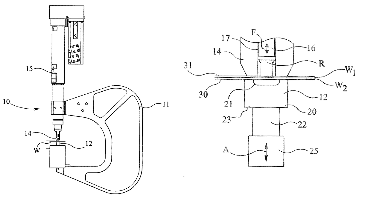
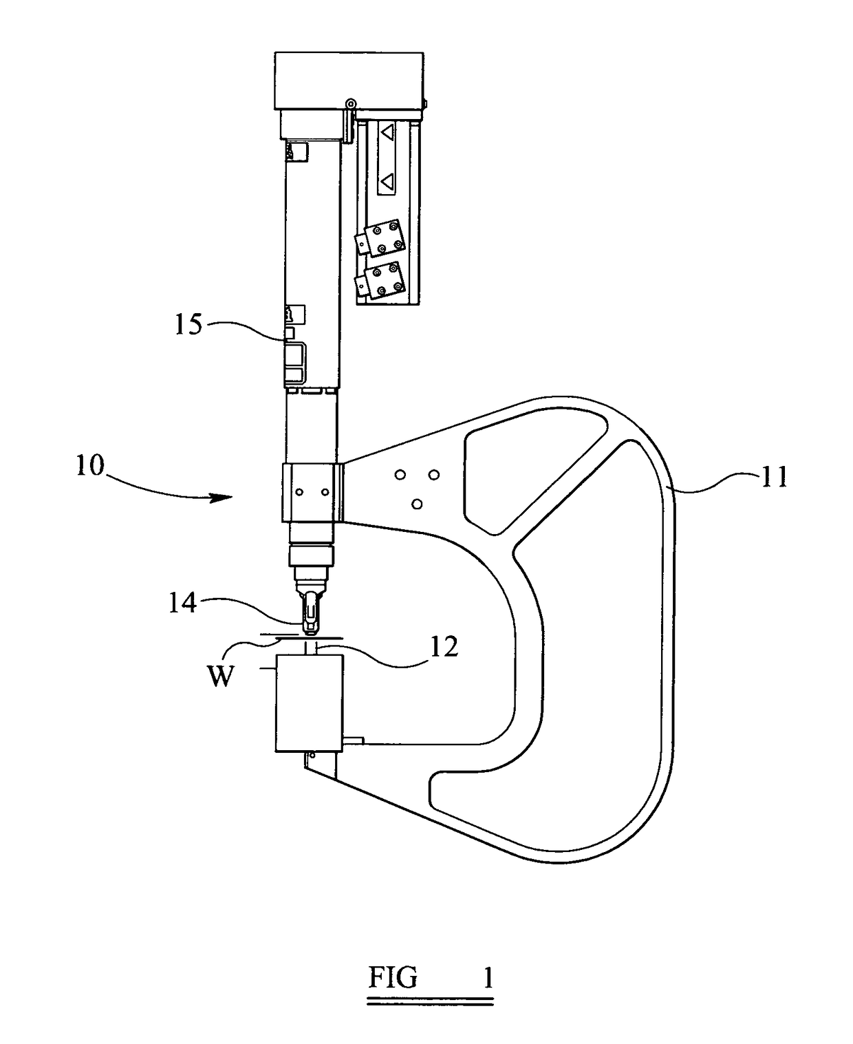
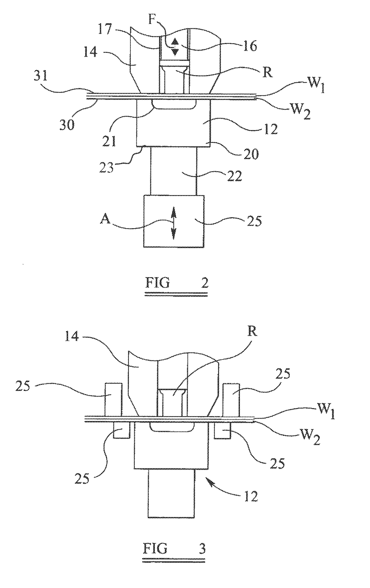
[0036]Referring now to FIGS. 1 and 2 of the drawings, a rivet setting tool 10 is mounted on an upper arm of conventional C-frame 11 above a rivet-upsetting die 12 supported in the lower arm. Self-piercing rivets R (one shown in FIG. 2 only) are inserted by the tool 10 into workpieces W (FIG. 2) supported over the die 12 as is well known in the art. It is to be appreciated that whilst the specific embodiment described herein relates to the feeding and insertion of rivets it has application to other fasteners that are inserted into workpieces using a die such as, for example, slugs.

[0037]The C-frame 11 is mounted on a robot manipulator (not shown) such that it is movable with the tool 10 by the robot towards and away from the workpieces W as required. Feed apparatus (not shown) alongside the C-frame 11 is designed to supply rivets R to the setting tool 10 in a predetermined and controllable fashion from a bulk source. This may be achieved, by for example, using tape feed or a compress...


PUM

PropertyMeasurementUnit
frequencyaaaaaaaaaa
ultimate tensile strengthaaaaaaaaaa
ultrasonic frequencyaaaaaaaaaa

Abstract

A joint is produced in at least two overlapping workpieces using a joining tool including a punch reciprocally disposed in a cylinder. The workpieces are disposed between the tool and a die. The tool applies a compressive force to deform the workpieces into a joint at a joining area between the tool and die. Continuous ultrasonic energy is applied to at least one of the workpieces in the joining area for at least part of the time during production of the joint to increase the ductility of at least one of the workpieces in the joining area. This induces an acousto-plastic effect in the material being formed which temporarily reduces its strength so as to exhibit increased ductility. The joining method may be used in self-piercing riveting and clinching techniques and enables viable joints to be formed in high strength materials or thick sheets of material.

Description

CROSS-REFERENCE TO RELATED APPLICATIONS[0001]This application is a U.S. national phase application filing of International Patent Application No. PCT / GB2009 / 001572, filed Jun. 23, 2009, and published as WO 2010 / 012973 on Feb. 4, 2010, which claims the benefit of and priority to United Kingdom Patent Application No. 0813883.6, filed Jul. 30, 2008, the entire contents of each of the foregoing are incorporated herein by reference.BACKGROUND OF THE INVENTIONI. Field of the Invention[0002]The present invention relates to an apparatus and method for joining components together and more particularly, but not exclusively, to joining sheet material such as metals using rivets or the like.II. Description of Related Art[0003]Self-piercing riveting (SPR) is a well-established technique for joining together components such as, for example, sheet metal. A self-piercing rivet typically comprises a head and a partially hollow cylindrical shank that terminates in an annular piercing edge and is inse...

Claims


Application Information

Patent Timeline
Patent Type & Authority Patents(United States)
IPC IPC(8): B21J15/02B21J15/12
CPCB21J15/025B21J15/12Y10T29/5377Y10T29/49956
Inventor CLARKE, CHRISTOPHER JAMESDOO, ROGER STANTONLUCAS, MARGARETTRINICK, RUSSELL JOHN
Owner ATLAS COPCO IAS UK LIMITED
Learn More