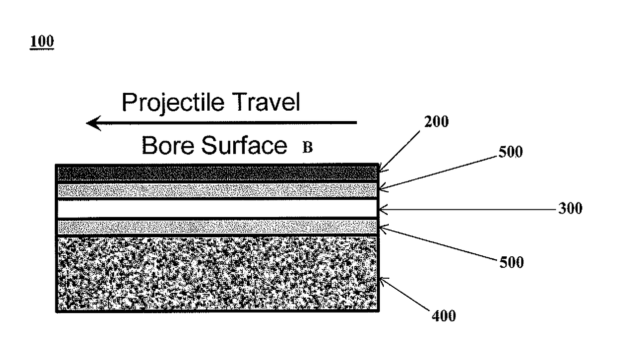
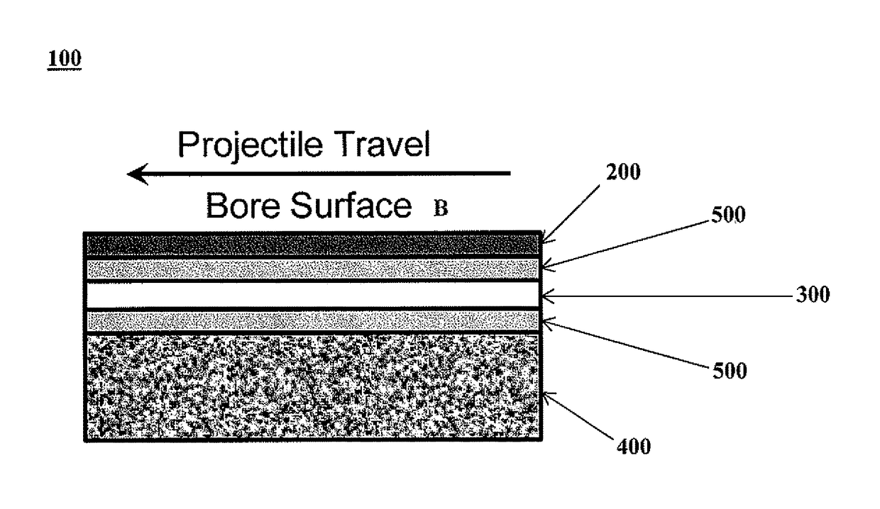
[0010]Disclosed herein is a mortar tube defined by a muzzle end, a breech end and a seamless rigid wall along the longitudinal axis encasing a hollow bore. The rigid wall is comprised of multiple heterogeneous layers having the main elements of 1) an inner bore facing layer, 2) an intermediate ceramic based thermal barrier layer and 3) an outer shell layer. The plurality of layers are cohesively integrated with each other in a seamless manner to yield a rigid and immobile mortar tube wall.
[0011]The improved mortar tube meets the same performance specifications of standard steel or superalloy mortar tubes. The multi-layered mortar tube allows for firing of the same ammunition, at the same firing rate and the same wear life but without the added weight of comparable steel mortar tubes. Such improved mortar tube weigh at least 30-70% less compared to legacy steel tubes. This permits the soldier to carry less weight thereby increasing maneuverability and freeing up the weight burden to carry other important equipment.
[0012]FIG. 1, illustrates a sectional view of an exemplary mortar tube wall of the present invention (not to scale) comprising a plurality of layers; with a first inner bore facing layer 200 closest to the inner bore B, a second thermal barrier layer 300 comprising a ceramic base material, and a third structural outer shell layer comprised of fiber reinforced composite material 400. Optional bonding layers 500 may be used to adhere the multiple layers together to form a cohesively integrated wall structure.
[0013]Inner Bore Facing Layer
[0014]The inner bore facing layer of the layered mortar tube is proximate to the hollow bore. It may be comprised essentially of a metal material having a melting point greater than 800° C., and preferably greater than 1200° C. Representative metals contemplated for use as the inner bore facing layer include Fe, Co, Ni, Cu, Al, Ti, Cr, V, Mo, Ta, W, Nb, etc. as well as alloys of each such as steel, stainless steel, nickel or cobalt alloys/superalloys, titanium alloys, refractory alloys, etc. Preferred metal materials include high strength gun steel, Ni or Co based superalloys, various types of stainless steel, refractory alloys, with Inconel 718® (nickel-based superalloy) or equivalent being more preferred. The thickness of the inner bore facing layer may be 0.003″-0.020″ thick.
[0015]Thermal Barrier Layer
[0016]An intermediate thermal barrier layer comprising of ceramic material is placed between the inner bore facing layer and outer shell layer. The thermal barrier layer functions to prevent heat from transferring from the inner bore facing layer to the outer shell layer and to reduce the peak temperature that the composite material (outer shell layer) experiences. It is comprised of ceramic materials including but not limited to yttria-stabilized zirconia, ceria-stabilized zirconia, alumina, mullite, zirconates, silica, polymer-derived ceramics (e.g. polysiloxanes, polycarbosiloxanes) and combinations thereof. The thickness of the intermediate ceramic layer is about 0.003″-0.050″.
[0017]Outer Shell Layer
[0018]The outer shell layer may be comprised of fiber reinforced composite material, which consists of a matrix reinforced with continuous fibers. This layer completely encloses the intermediate (thermal barrier) layer. The matrix material can be polymer, metallic or ceramic based. Fibers that could be used as reinforcement include but are not limited to carbon fiber (T700, IM7, IM9, T300, T1000, etc), Nextel (Al2O3), SiC, boron, and fiberglass. The wall thickness of the outer shell layer need not be a uniform thickness. The thickness of the outer shell layer is about 0.05″-0.3″ and may be adjusted along its length based on the pressure travel curve. Thus, the outer shell layer may be thinner at the muzzle end than at the breach end to accommodate the varying pressure forces applied at each end when the mortar is fired. It is preferred that the outer shell layer has a greater thickness than the inner or intermediate layer.
[0019]Bonding Layers
[0020]Bonding layers may be optionally applied to adhere the thermal barrier layer to the bore facing layer and outer shell layer as well as reducing the expansion coefficient gradient between the ceramic layer and the inner and outer layers. The bonding layer may be composed of MCr, MAl, or MCrAlY, wherein M is a metal selected from the group consisting of nickel or cobalt, and Cr is chromium, Al is aluminum and Y is yttrium. A bonding layer comprised of MAl may preferably be used to bond the outer layer to the thermal barrier layer. The thickness of each bonding layer should be limited to 0.005″ maximum (and more ideally 0.003″) for optimal weight savings.
[0021]Exemplary Multi-Layered Wall Configuration
[0022] TABLE 1 sets forth the configuration and composition of a preferred mortar tube embodiment. Layer Dimensions Composition 1 Inner (facing ~0.003″-0.015″ Nickel-based superalloy the bore) (Inconel 718 ®) 2 Intermediate ~0.002″-0.050″ Ceramic base material (e.g. thermal yttria-stabilized zirconia, barrier ceria-stabilized zirconia, alumina, silica) plus optional bond-coats 3 Outer shell ~0.05″- 0.3″ High strength aluminum layer matrix composites or high temperature polymer matrix composites (e.g. MetPreg ®or PyroSic ®)
[0023]Process
[0024]One approach for obtaining a multi-layered architecture is to begin with a seamless metal tube (preferably steel, nickel or cobalt and alloys of such) as the inner bore facing layer. The intermediate thermal barrier layer can be applied to the inner layer by conventional air plasma spray (APS) in the following sequence, (1) clean and abrasive grit blast the outer surface of the metal tube, (2) apply inner layer bond coat via APS to a thickness of 0.003-0.005″, (3) apply yttria-stabilized zirconia thermal barrier layer via APS to a thickness of 0.005-0.008″, (4) apply outer layer bond coat via APS to a thickness of 0.003-0.005″.
[0025]The thermal barrier layer and its associated bonding layers can also be applied directly to the outer-surface of inner bore facing layer by common thermal/plasma spray, laser cladding, vapor deposition (e.g. electron beam physical vapor deposition), aqueous plating, shrink-fitting to a monolithic liner, high volume low pressure (HVLP) spray coating, or conventional spray painting techniques. Table 2 suggests several attachment methods with exemplary materials comprising the thermal barrier layer. Factors for selecting each of the attachment methods and materials may include maturity of the technology for such method, thermal shock requirements for the tube, environmental pollution, and costs.
[0026] TABLE 2 METHOD FOR THERMAL BARRIER ATTACHMENT LAYER MATERIAL Plasma spray Yttria stabilized zirconia (YSZ) based multilayers Laser Cladding Yttria stabilized zirconia (YSZ) Conventional or High Polymer-derived ceramic coatings (e.g. Volume Low polysiloxanes, polycarbosiloxanes), Pressure (HVLP) Cerakote ™ (NIC) and Spray Thermablock ™(MicroPhase) Electron Beam Physical Yttria Stabilized Zirconia Vapor Deposition (YSZ) based multilayers
[0027]Following APS application of the thermal barrier layer, the outer surface of the bi-layer (inner and intermediate layer) can be encased by the composite outer shell layer. This layer may be formed by any of the traditional composite processing techniques. For purposes of fabricating the composite outer shell layer, the bi-layer (inner and intermediate) is treated as a traditional substrate/mandrel. Typical process that can be used include but are not limited to filament winding, fiber placement, tape placement, vacuum assisted resin transfer molding (VARTM), resin transfer molding (RTM) and casting. The exact techniques used will depend upon the specific fiber/matrix combination chosen. If an aluminum matrix and Nextel (Al2O3) fibers are picked then wet winding with molten aluminum or casting are possible choices. For polymer matrix composite, filament winding or tape placement followed by autoclave cure are more likely to be used. Depending on the initial thickness of the inner bore facing layer, the inner bore diameter may require honing to achieve a desired final thickness and surface finish.
[0028]The fabricated multi-layered mortar is seamless, finless, lightweight, and has the same or better performance and life characteristics as the legacy mortar tubes composed of steel.
[0029]The embodiments set forth above are for illustrative purposes only and it is recognized that numerous variations may be made with respect to the process and materials for preparing the thermal barrier layered composite mortar. Therefore, while the invention has been disclosed in various forms only, it will be obvious to those skilled in the art that additions, deletions and modifications can be made without departing from the spirit and scope of this invention, and no undue limits should be imposed, except as to those set forth in the following claims.