
Traffic-light cycle length estimation device

a technology of cycle length and estimation device, which is applied in the direction of controlling traffic signals, instruments, computing, etc., can solve the problem that the cycle length cannot be estimated at an intersection where the traffic is light, and achieve the effect of easy estimation

Active Publication Date: 2018-04-17
TOYOTA JIDOSHA KK
View PDF7 Cites 3 Cited by
  • Summary
  • Abstract
  • Description
  • Claims
  • Application Information

AI Technical Summary

Benefits of technology

The patent describes a device that uses traffic lights to estimate the cycle time (the time it takes for vehicles to pass through an intersection) by analyzing the start times of vehicles. By using multiple start times from different directions, the device improves the accuracy of estimating the cycle length. This can be useful for improving traffic control and navigation systems.

Problems solved by technology

However, because the device described above assumes that there is always a vehicle that starts moving when the traffic light changes to green, the cycle length cannot be estimated at an intersection where the traffic is light.

Method used


Image

  • Traffic-light cycle length estimation device
  • Traffic-light cycle length estimation device
  • Traffic-light cycle length estimation device

Examples


first embodiment

[0035]A traffic-light cycle length estimation device in a first embodiment is described below with reference to the drawings.

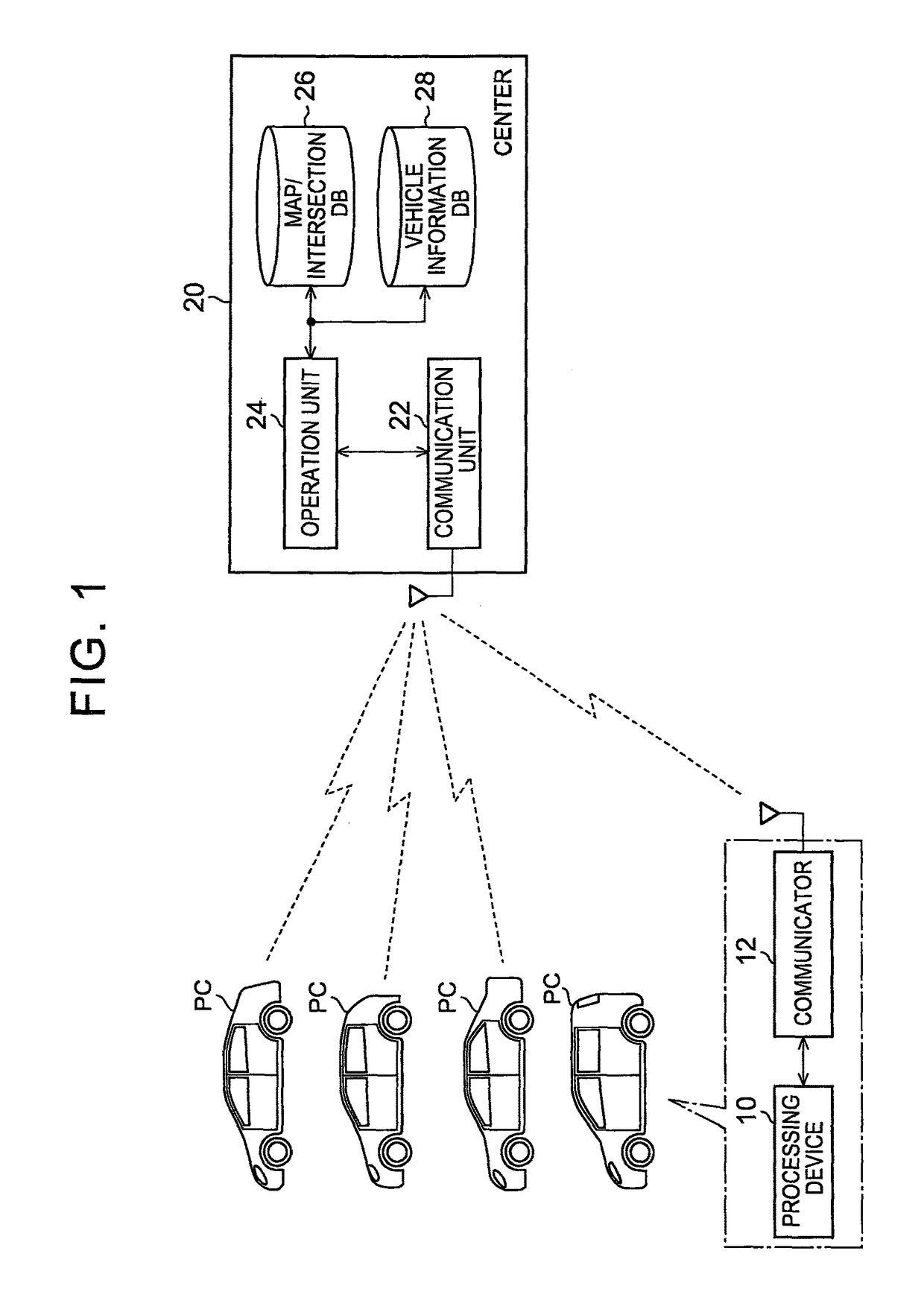
[0036]FIG. 1 shows the system configuration in the embodiment. In the system shown in the figure, a vehicle PC traveling on a road communicates with a center 20. In this system, a vehicle PC that can communicate with the center 20 includes a processing device 10 and a communicator 12. The processing device 10 is an electronic device that performs various types of operation processing. As the processing device 10, an electronic device having a navigation system is assumed. The communicator 12 is an electronic device that wirelessly communicates with a communication unit 22 provided in the center 20.

[0037]On the other hand, the center 20 includes the communication unit 22 that wirelessly communicates with the communicator 12, an operation unit 24 that performs various types of operation, a map / intersection database 26, and a vehicle information database 28.

[0038...

second embodiment

[0075]A second embodiment is described below with reference to the drawings with focus on the difference from the first embodiment.

[0076]In this embodiment, the processing in step S42 in FIG. 7 is performed by the processing in FIG. 11 instead of the processing in FIG. 8. In FIG. 11, the same step number is used for the processing corresponding to that in FIG. 8 for the sake of convenience.

[0077]When the processing in step S50 is completed in the processing shown in FIG. 11, the operation unit 24 receives the start intervals in the histogram generated by the processing in step S16 in FIG. 3 and calculates the greatest common divisor using the least-squares method (S52a). That is, the operation unit 24 calculates the variable Δ that minimizes the sum of squares of the difference between each of the start intervals X1, X2, X3, . . . and each of the integral multiple values of the variable Δ (n1·Δ, n2·Δ, n3·Δ, . . . ) and sets the calculated result to the greatest common divisor. The i...


PUM


Abstract

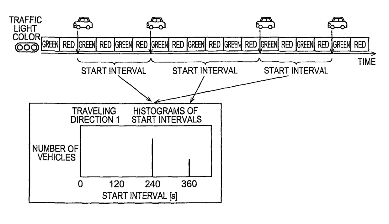
For each of the traveling directions (traveling direction 1 to traveling direction 4) at an intersection, a traffic-light cycle length estimation device acquires a time at which a vehicle in the stopped state starts moving, calculates the time difference between neighboring start times, which have been acquired, as a start interval, and generates a histogram based on the number of samplings of start intervals. The device combines the generated histograms into a histogram for all direction to generate one histogram that represents the relation between the start intervals and the number of samplings and, based on this histogram, estimates the cycle length of the traffic light. If a particular value, one of the start intervals, corresponds to the maximum number of samplings, that particular value is estimated as the cycle length.

Description

BACKGROUND OF THE INVENTION[0001]1. Field of the Invention[0002]The present invention relates to a traffic-light cycle length estimation device for estimating a cycle length that is a time interval from the time the traffic light color changes to green to the time the traffic light color changes back to green via yellow and red.[0003]2. Description of Related Art[0004]A traffic-light information estimation device for estimating a cycle length is proposed, for example, in Japanese Patent Application Publication No. 2009-116508 (JP 2009-116508 A). The cycle length refers to a time interval from the time the color of a traffic light, installed at an intersection, changes to green to the time the color of the traffic light changes back to green via yellow and red. This device estimates the cycle length of a traffic light, based on the time difference between the time a vehicle in the stopped state at an intersection starts moving when the traffic light changes to green and the time a ve...

Claims


Application Information

Patent Timeline
Patent Type & Authority Patents(United States)
IPC IPC(8): G06N7/00G08G1/08G08G1/097G08G1/01
CPCG08G1/0129G08G1/097G08G1/08G08G1/0112
Inventor MURAI, RIE
Owner TOYOTA JIDOSHA KK
Learn More