Power supply circuit and power supply method

a power supply circuit and power supply method technology, applied in the direction of emergency power supply arrangements, transportation and packaging, dc source parallel operation, etc., can solve the problem of not considering a part of energy, and achieve the effect of maximizing the working time of peripheral devices and efficiently utilizing remaining power in the computer or information processing devi

Active Publication Date: 2018-04-24
MEMBLAZE TECH BEIJING
View PDF13 Cites 0 Cited by
  • Summary
  • Abstract
  • Description
  • Claims
  • Application Information

AI Technical Summary

Benefits of technology

[0005]However, when a power source or power supply circuit of a computer or an information processing device is down, or a computer indicates a power-off event to peripheral devices, the power supplied to the peripheral devices is not stopped immediately. As there are power repository elements such as capacitors in circuits such as the power source or a mainboard, the power repository elements are able to provide electricity even after the power is off. However, in the prior art, this part of energy is ignored. According to the technical solution of this invention, the peripheral devices are able to detect the power-off state of the computer, and then utilize remaining power in the computer or the information processing device efficiently. Therefore, the working time of the peripheral devices are increased.

Problems solved by technology

However, in the prior art, this part of energy is ignored.

Method used


Image

  • Power supply circuit and power supply method
  • Power supply circuit and power supply method
  • Power supply circuit and power supply method

Examples


first embodiment

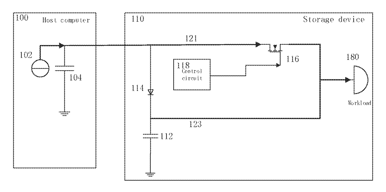
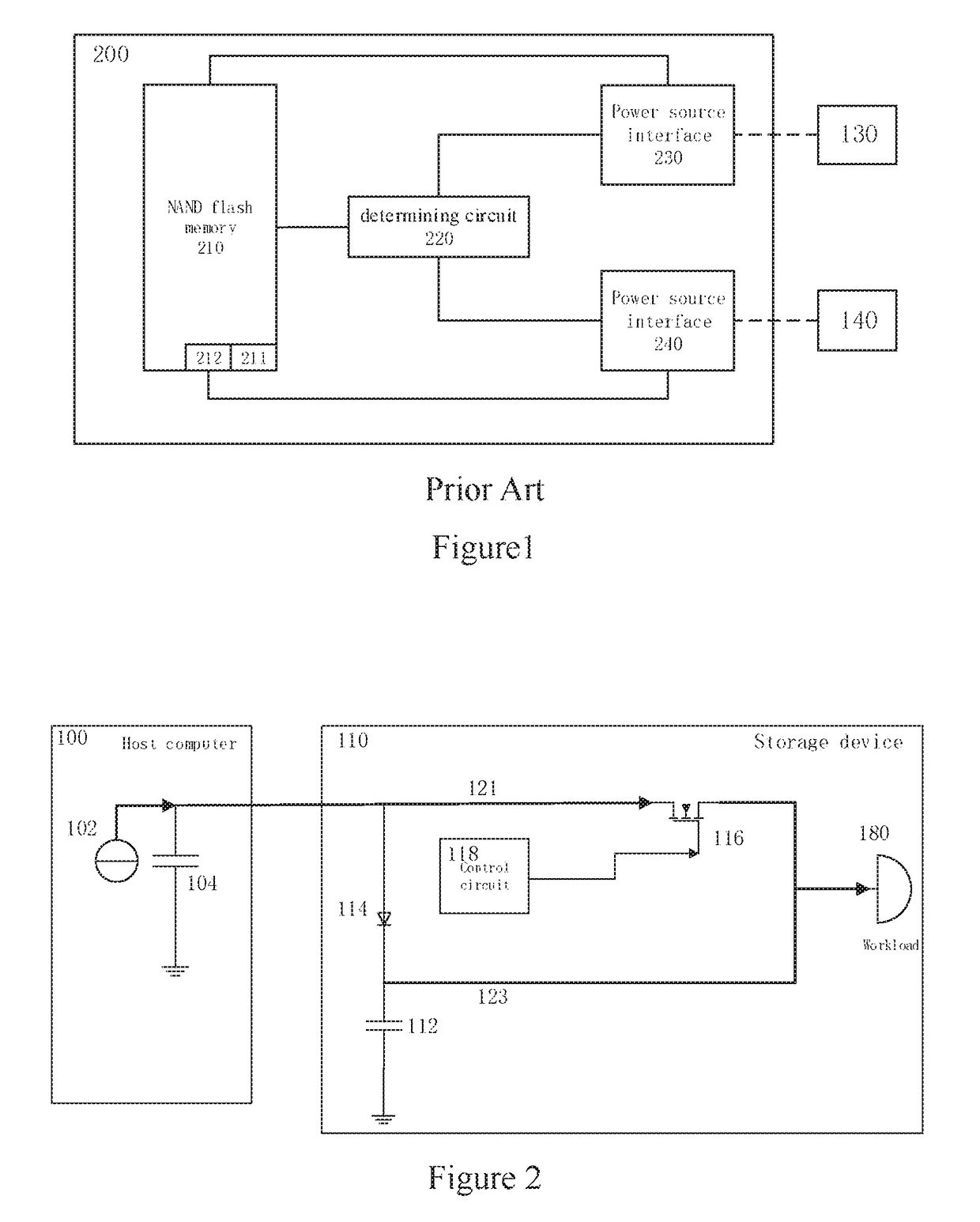
[0031]FIG. 2 is a schematic diagram of the power supply circuit of a peripheral device according to the present invention. The embodiment illustrated in FIG. 2 includes a host computer 100 and a storage device 110 coupled to the host computer 100. The host computer 100 can be coupled to the storage device 110 in various ways. The coupling ways used to connect the host computer 100 and the storage device 110 include but not limited to, e.g., SATA, IDE, USB, PCIE, SCSI, Ethernet, Fiber Channel and Wireless communication network. The host computer 100 is an information processing device, such as a personal computer, a tablet computer, a server, a portable computer, a network switch, a router, a cellular phone and a personal digital assistant (PDA), which can communicate with the storage device in one or more of the above discussed ways. The person skilled in the art can realize that other types of peripheral devices, such as network adapter or graphic adapter, can utilize the power sup...

second embodiment

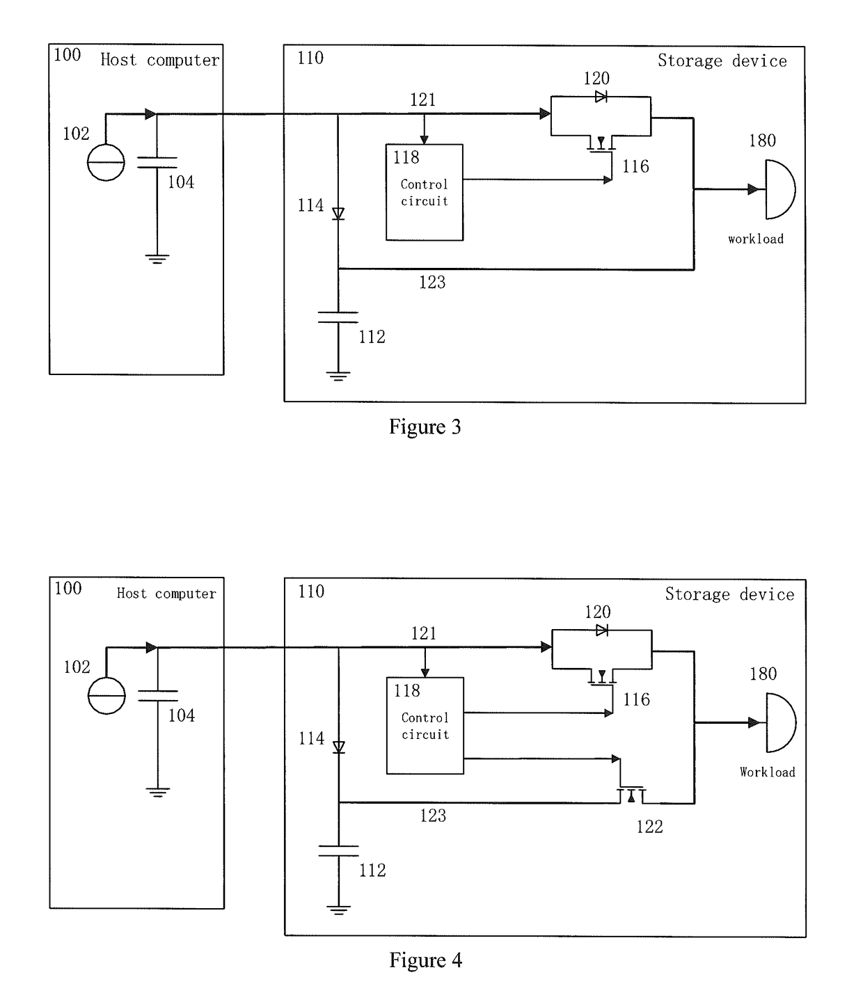
[0038]FIG. 3 is a schematic diagram of the power supply circuit of a peripheral device according the present invention. The power supply circuit in the FIG. 3 is similar to the power supply circuit presented in FIG. 2. The difference is that there is a diode 120 in FIG. 3. The on-state resistance of the diode 120 is bigger than the on-state resistance of the N-channel MOSFET 116. Accordingly when the power source 102 works normally, the control circuit 118 controls the N-channel MOSFET 116 as a switch to turn-on, such that the electricity energy from the power source 102 is supplied to the workload 180 via the N-channel MOSFET 116. When the control circuit 118 measures the voltage of the power supply path 121 from the power source 102 and determines the power source 102 is off, the control circuit 118 output a control signal to turn-off the N-channel MOSFET 116. The output voltage of the power supply path 121 from the power source 102 can turn-on the diode 120, such that the electri...

third embodiment

[0039]FIG. 4 is a schematic diagram of the power supply circuit of a peripheral device according the present invention. The power supply circuit in the FIG. 4 is similar to the power supply circuit presented in FIG. 3. The difference is that there is an N-channel MOSFET 122 in FIG. 4. When the control circuit 118 determines the power source 102 works normally by measuring the output voltage of the power supply path 121 from the power source 102, the control circuit 118 turns on the N-channel MOSFET 116 (as a switch) and outputs a control signal to turn-off the N-channel MOSFET 122 (as a switch), such that the electricity energy from the power source 102 is provided to the workload 180 via the N-channel MOSFET 116. When the control circuit 118 determines the power source 102 is down by measuring the output voltage of the power supply path 121 from the power source 102, the control circuit 118 outputs a control signal to turn-off the N-channel MOSFET 116, and outputs a control signal ...


PUM


Abstract

A power supply circuit coupled to a power source for providing electronic energy to a workload includes a first switch, a control circuit, a first diode, and a backup power, in which the input of the first switch is coupled to the power source, the output of the first switch is coupled to the workload, the control circuit is coupled to the control terminal of the first switch for determining the state of the power source, the anode of the first diode is coupled to the power source, the cathode of the first diode is coupled to the first terminal of the backup power, the first terminal of the backup power is further coupled to the workload, when the control circuit determines that the power source is in a power-off state, a control signal is applied to the control terminal of the first switch to turn off the first switch.

Description

TECHNICAL FIELD[0001]This invention relates to a Solid-State Storage Device (SSD), particularly relates to a power supply circuit and a power supply method for a storage device.BACKGROUND[0002]Computer peripheral devices are connected to a computer via various interfaces. In most cases, computer interfaces provide not only a data path between a computer and peripheral devices, but also power from the computer to the peripheral devices. Therefore, in cases that the computer is powered off, the peripheral devices connected to the computer lose their power supply.[0003]China patent CN101710252B discloses a solution of avoiding data loss in a buffer memory of a storage device in the case of an unexpected power-off. In this solution, a backup power is provided in the storage device. When an unexpected power-off occurs, the backup power provides temporary electricity to forward and store the data in the buffer memory (cache) to a flash memory. US patent U.S. Pat. No. 8,031,551B2 discloses...

Claims


Application Information

Patent Timeline
Patent Type & Authority Patents(United States)
IPC IPC(8): H02J1/10H02J7/34H02J9/06
CPCH02J1/108H02J9/061H02J7/34Y10T307/625
Inventor NI, YONG
Owner MEMBLAZE TECH BEIJING
Why Eureka
Try Eureka