Electromagnetic pump

a technology of electromagnetic pump and shock absorber, which is applied in the direction of pump, positive displacement liquid engine, machine/engine, etc., can solve the problems of reduced shock absorber, insufficient durability, and inconvenient cost, so as to improve shock absorber performance, and reduce the effect of shock absorber

Active Publication Date: 2018-05-01
AISIN AW CO LTD
View PDF23 Cites 0 Cited by
  • Summary
  • Abstract
  • Description
  • Claims
  • Application Information

AI Technical Summary

Benefits of technology

[0014]In the electromagnetic pump, the elastic member is provided to at least one of the distal-end portion of the piston and the specific portion of the support member, which face each other, and the distance between the specific portion of the support member and the distal-end portion of the piston is set to be shorter than the distance between the plunger and the core when the electromagnetic portion is stationary so that the distal-end portion of the piston collides against the specific portion of the support member via the elastic member when the electromagnetic portion is driven to move the piston forward. Consequently, a shock of the collision is absorbed by the elastic member, which effectively suppresses generation of a collision sound. Because it is not necessary to constitute the elastic member from a non-magnetic body, in addition, the range of material selection is widened, which makes it possible to improve the durability and reduce the cost. Because there is an abundant arrangement space compared to a configuration in which the elastic member is disposed in the electromagnetic portion, sufficient shock absorbing performance can be obtained by disposing an elastic member with appropriate performance. As a result, it is possible to appropriately relieve a shock accompanied by drive of the electromagnetic portion to suppress generation of an abnormal sound.
[0015]In the present electromagnetic pump according to an exemplary embodiment, the support member may be formed with a support portion that supports the spring, and a projecting portion that projects toward the distal-end portion of the piston with respect to the support portion; and the specific portion may be a projecting end surface of the projecting portion. Accordingly, the distance between the specific portion of the support member and the distal-end portion of the piston can be easily controlled while securing a necessary urging force of the spring.
[0016]In the electromagnetic pump according to the exemplary embodiment, in addition, the spring may be a coil spring; the distal-end portion of the piston may be formed as a cylindrical portion with an annular cylindrical end surface configured to receive an urging force of the coil spring; the elastic member may be a plate spring attached so as to cover an opening of the cylindrical portion; and the specific portion of the support member may be formed such that an outside diameter of the specific portion is smaller than an inside diameter of the cylindrical portion. Accordingly, elongation of the axial length of the electromagnetic pump can be suppressed by using a plate spring as the elastic member.
[0017]In the electromagnetic pump according to an exemplary embodiment in which the elastic member is a plate spring, an inner peripheral edge of the cylindrical end surface of the cylindrical portion of the piston may be chamfered. Accordingly, the elastically deformable region of the plate spring can be expanded without increasing the diameter of the piston, which further improves the shock absorbing performance. As a result, generation of an abnormal sound can be more reliably suppressed.
[0018]In the electromagnetic pump according to an exemplary embodiment in which the elastic member is a plate spring, in addition, the plate spring may include a disc portion that covers the opening of the cylindrical portion, and a plurality of leg portions that extend along an axial direction of the cylindrical portion from an outer peripheral edge of the disc portion. In the electromagnetic pump according to such an embodiment, the disc portion and the leg portions of the plate spring may be formed integrally, and the plate spring may be provided with cut-away portions formed on both sides of a root of the leg portions. Accordingly, sufficient flatness can be secured in the vicinity of the outer peripheral edge of the disc portion even if the leg portions are bent along the axial direction of the cylindrical portion of the piston, which improves the ease of assembly of the plate spring.
[0019]In the electromagnetic pump according to an exemplary embodiment in which the plate spring includes a disc portion and a plurality of leg portions, the piston may be moved back and forth to suction the working fluid via a suction check valve and discharge the suctioned working fluid via a discharge check valve; the discharge check valve may be built in the cylindrical portion of the piston; and the plate spring may be provided with a plurality of communication holes formed in a surface of collision that collides against the specific portion of the support member, the plurality of communication holes allowing the working fluid to flow into the discharge check valve. In the electromagnetic pump according to such an embodiment, the communication holes may be formed in the disc portion in a generally elliptic shape with long sides extending in a circumferential direction and with short sides extending in a radial direction. Accordingly, the working fluid can be caused to smoothly flow into the discharge check valve via the plate spring. In the electromagnetic pump according to such an embodiment, in addition, three communication holes may be formed at equal angular intervals in the circumferential direction. Accordingly, a stress can be dispersed when the plate spring receives an impact, which secures the durability of the plate spring. In the electromagnetic pump according to such an embodiment, further, the same number of communication holes and leg portions may be formed at equal angular intervals in the circumferential direction with the corresponding communication holes and leg portions arranged in radial directions. When the plate spring receives an impact, a stress concentrates on narrow portions between adjacent communication holes. Thus, the durability of the plate spring can be further improved by forming the leg portions at positions far from such portions. In the electromagnetic pump according to such an embodiment, in addition, the suction check valve may be built in the support member; and the suction check valve and the discharge check valve may be coaxially disposed on an axis of reciprocal motion of the piston.

Problems solved by technology

Thus, sufficient durability may not be secured, and the cost may not be advantageous.
Because it is necessary to dispose the shock absorbing member in a limited space of the electromagnetic portion, in addition, it is inevitable that the shock absorbing member is reduced in size more than necessary, and sufficient shock absorbing performance may not be obtained.

Method used


Image

  • Electromagnetic pump
  • Electromagnetic pump
  • Electromagnetic pump

Examples


Embodiment Construction

[0026]Now, a mode for carrying out the preferred embodiments will be described.

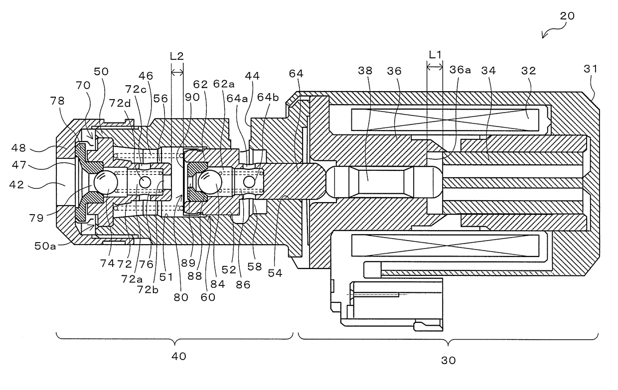
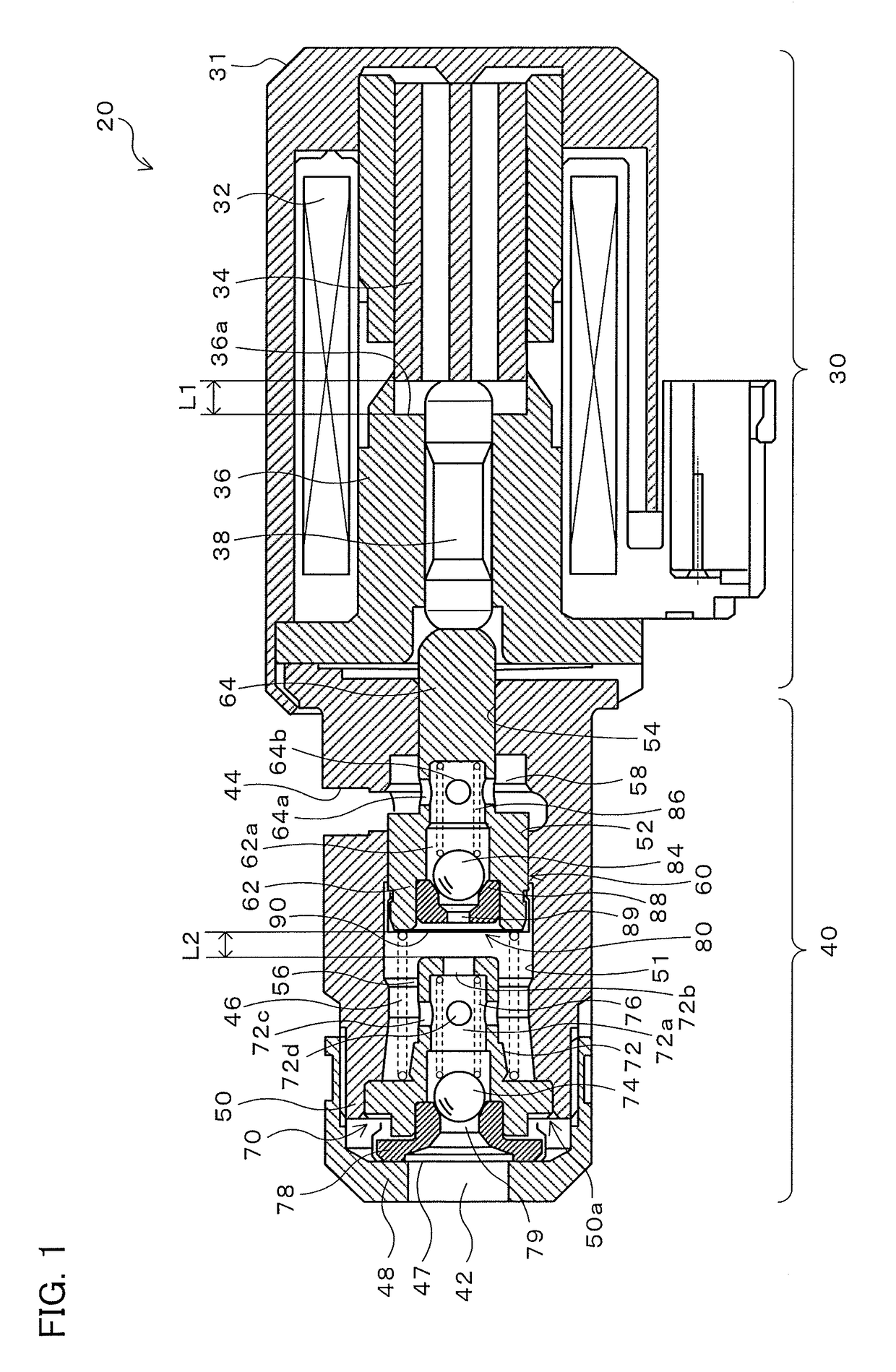
[0027]FIG. 1 is a diagram illustrating a schematic configuration of an electromagnetic pump 20 according to an embodiment. The electromagnetic pump 20 according to the embodiment includes a solenoid portion 30 that generates an electromagnetic force, and a pump portion 40 actuated by the electromagnetic force of the solenoid portion 30. The electromagnetic pump 20 is configured as a pump that supplies a predetermined stand-by pressure to a friction engagement element for starting, among friction engagement elements provided in an automatic transmission, when an engine is stopped in an automobile on which the engine and the automatic transmission are mounted and which has an idling stop function for stopping the engine when an engine stopping condition such as a vehicle speed of less than a predetermined vehicle speed is met and for starting the engine which has been stopped when an engine starting conditi...


PUM


Abstract

A plate spring is attached to the distal-end portion of a piston. The distance L1 between the distal-end portion of a plunger and a core (recessed portion) that faces the distal-end portion of the plunger is set to be shorter than the distance L2 between the distal-end portion (plate spring) of the piston and the projecting end surface of a valve main body that faces the distal-end portion of the piston with drive of a solenoid portion stopped. Consequently, when the solenoid portion is driven, the plate spring collides against the projecting end surface of the valve main body so that the plunger does not collide against the core. As a result, a shock applied to the piston can be absorbed by the elastic force of the plate spring, which suppresses generation of a sound of collision.

Description

CROSS REFERENCE TO RELATED APPLICATIONS[0001]This application is a National Stage of International Application No. PCT / 2013 / 079260 filed Oct. 29, 2013, claiming priority based on Japanese Patent Application No. 2012-240573 filed Oct. 31, 2012, the contents of all of which are incorporated herein by reference in their entirety.TECHNICAL FIELD[0002]The subject matter described hereinrelates to an electromagnetic pump in which a piston is moved back and forth to suction and discharge a working fluid.BACKGROUND ART[0003]Hitherto, there has been proposed an electromagnetic pump of this type, including: a piston; an electromagnetic portion that attracts a plunger to a core using an electromagnetic force to move the piston forward; a spring that applies an urging force that is opposite in direction to the electromagnetic force to move the piston in reverse; an end plate that supports the spring; a suction check valve built in the end plate; and a discharge check valve built in the piston (...

Claims


Application Information

Patent Timeline
Patent Type & Authority Patents(United States)
IPC IPC(8): F04B17/03F04B7/02F04B17/04
CPCF04B17/03F04B17/04F04B7/02
Inventor ISHIKAWA, KAZUNORIKOKUBU, TAKAHIRONAKAI, MASAYAISHIKAWA, TOMOMI
Owner AISIN AW CO LTD
Why Eureka
Try Eureka