
Base for sanding machines, grinding machines or the like

a technology for sanding machines and grinding machines, applied in the direction of grinding machines, castors, transportation and packaging, etc., can solve the problems of sanding and grinding machines being practically impossible even for the most skilled operators, affecting the practicality of use of operators, and affecting the use of portable devices. to achieve the effect of improving the practicality of us

Inactive Publication Date: 2018-05-22
UNIBASE SPA
View PDF16 Cites 5 Cited by
  • Summary
  • Abstract
  • Description
  • Claims
  • Application Information

AI Technical Summary

Benefits of technology

The base ensures consistent pressure and angular position of the tool, reducing operator effort and improving machining quality by distributing weight evenly and allowing for precise adjustments, resulting in smoother, defect-free surfaces.

Problems solved by technology

However, these prior art portable grinding machines, when used on substantially flat surfaces, have some limits and drawbacks.
With prior art portable sanding and grinding machines this is practically impossible even for the most skilled operators as, without the aid of any reference, these parameters are controlled and managed in an entirely manual manner based on the sensitivity of the operator's limbs.
Moreover, handling of these portable devices is made even more difficult by the torque that is transmitted to the body of the machine by the tool when it comes into contact with the surface to be machined.
Therefore, the operator, who already has to oppose rotation of the machine body, also has the difficult task of correctly metering the pressure of the tool and of correcting its angle with precision.
Consequently, surfaces machined with these devices always have various imperfections, such as ridges, dips and areas with different degrees of roughness.
Moreover, with these prior art machines, machining operations on flat surfaces, even of limited dimensions, requires considerable mental and physical effort by the operator.
Just as in the case of portable machines, also in this case it is difficult or even impossible to maintain a constant thrust on the handle in order to maintain a constant pressure exerted on the surface to be sanded / polished.
With prior art portable and semi-portable sanding machine it is therefore difficult to obtain a machined surface without defects, which are more accentuated when the operator lacks experience.

Method used


Image

  • Base for sanding machines, grinding machines or the like
  • Base for sanding machines, grinding machines or the like
  • Base for sanding machines, grinding machines or the like

Examples


Embodiment Construction

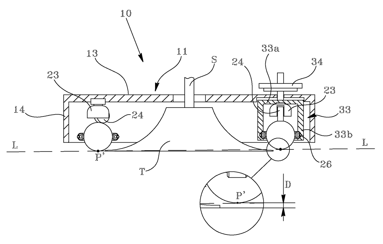
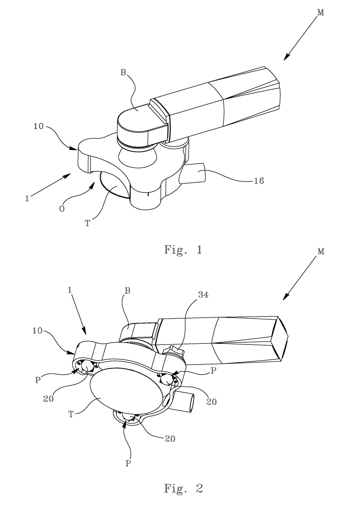
[0042]With reference to the accompanying FIGS. 1 and 2, there is illustrated a base for sanding or grinding machines, indicated as a whole with 1, applied to a sanding / grinding machine M.

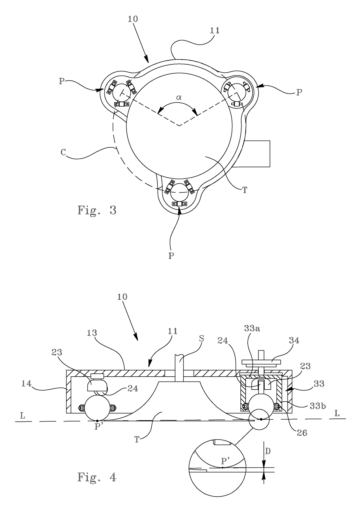
[0043]In detail, the base 1 according to the invention comprises a body 10 provided with at least three supports P arranged around a tool T of the machine. As already mentioned, said tool T can comprise one or more rotating discs on which accessories can be mounted to perform different types of machining operations, such as sanding, grinding, brushing, polishing, etc.

[0044]In the example illustrated, the machine M comprises a single rotating disc T.

[0045]According to a preferred embodiment, said supports P are arranged along a circumference C having a larger diameter with respect to that of the tool T and the centre of which preferably coincides with the rotation axis of said tool.

[0046]Even more preferably, said supports P can be arranged spaced angularly at equal distances from one another on said...


PUM


Abstract

A base for sanding machines, grinding machines or the like includes a body (10) connectable to a machine (M) or integral therewith, the body (10) being provided with at least three supports (P) arranged in such a manner that their ends (P′) lie on a plane (L) and configured in such a manner that at least one tool (T) of the machine projects at least partly beyond the plane (L) by a portion (D), the body (10) being provided with elements adapted to vary the position of the plane (L) with respect to the tool (T).

Description

FIELD OF THE INVENTION[0001]The present invention relates to a base for sanding machines, grinding machines or the like and in particular a base for disc sanding machines or grinding machines.[0002]More in detail, the invention relates to an omnidirectional sliding base for portable or semi-portable sanding or grinding machines adapted to facilitate their use on flat surfaces.[0003]The invention also relates to a sanding or grinding machine provided with this base.BACKGROUND OF THE INVENTION[0004]There are known on the market various types of disc sanding or grinding machines to perform cleaning, polishing, grinding or brushing operations on substantially flat surfaces made of stone, wood, metal, glass or composite materials.[0005]These machines generally comprise one or more discs or plates (to which different tools, with different degrees of abrasion, are fitted), which are rotated around their axis, around an orbit, or both, and which, in contact with a surface, perform one of th...

Claims


Application Information

Patent Timeline
Patent Type & Authority Patents(United States)
IPC IPC(8): B24B41/02B24B41/047B24B23/02B24B55/05B24B55/10
CPCB24B41/02B24B23/028B24B55/102B24B55/052B24B41/047B60B19/003B60B33/08
Inventor MOLLONE, PASQUALE
Owner UNIBASE SPA
Learn More