Fluid coupling

a technology of fluid coupling and fluid, which is applied in the direction of rotating vibration suppression, gearing, springs/dampers, etc., can solve the problems of reducing affecting so as to achieve efficient radiation, reduce the axial length of the fluid coupling, and improve the durability of the lockup clutch

Active Publication Date: 2018-05-29
TOYOTA JIDOSHA KK
View PDF18 Cites 0 Cited by
  • Summary
  • Abstract
  • Description
  • Claims
  • Application Information

AI Technical Summary

Benefits of technology

[0008]The present invention was made in view of the aforementioned technical problems and has an object to provide a fluid coupling which effectively utilizes an internal space of the cover member and in which a device for damping torsional vibration provided inside the cover member can sufficiently exert performances of vibration damping.
[0015]As described, the driven impeller, the damper mechanism, the lockup clutch, and the pendulum damper are arranged in order in the axial direction of the rotary shaft in the cover member. Consequently, the axial length of the fluid coupling can be reduced.
[0016]Moreover, in the axial direction, since the plate member serving as an engagement surface of the lockup clutch is arranged between the damper mechanism and the pendulum damper in the axial direction, the internal space in the radial direction between the driven impeller and the cover member can be utilized to arrange the damper mechanism therein and, the internal space of the cover member in the radial direction can be utilized as a space for arranging the pendulum damper. That is, since the pendulum damper and the first cover member are arranged so as to face each other in the radial direction, the space for arranging the pendulum damper is not interfered with the structure of the damper mechanism or the lockup clutch. Therefore, since the pendulum damper can be utilized the internal space of the cover member in the radial direction, the distance from the rotation center of the rotary member of the pendulum damper to the inertial mass can be made larger, and an inertial moment by the pendulum damper acting on the output member can be made larger. That is, the internal space of the fluid coupling can be effectively utilized, and the damping performance of the torsional vibration by the pendulum damper can be sufficiently exerted. Moreover, since a fluid such as operating oil is also interposed on a rear side of the engagement surface of the lockup clutch, heat generated on the engagement surface of the lockup clutch can be efficiently radiated from the plate member, whereby durability of the lockup clutch can be improved.
[0017]Moreover, the plate member provided on the second cover member and the piston of the lockup clutch are integrated in a manner to divide a first chamber accommodating the drive and driven impellers and the second chamber accommodating the pendulum damper when the lockup clutch is engaged. Therefore, during engagement, the fluid pressure can no longer be transmitted to the pendulum damper easily, and prevention of a pendulum motion of the inertial mass by the fluid pressure can be suppressed. That is, drop of the damping performance of the torsional vibration in the pendulum damper by the fluid pressure inside the cover member can be suppressed.

Problems solved by technology

A rotary member such as a driving shaft and a gear for transmitting a torque generated in a power source to an intended spot or member unavoidably vibrates due to fluctuation of the input torque itself, fluctuation of a load or friction.
A frequency of the vibration changes in accordance with a rotation speed and since higher-mode vibration of secondary vibration or more is generated at the same time, amplitude becomes larger by resonance and hence, noise or deterioration of durability can be caused.
That is, inside the cover member, the space for arranging the device for damping the torsional vibration is restricted.
However, in the structure described in Japanese Patent Laid-Open No. 2012-77823, an engagement portion connecting the dynamic damper and the lockup piston covers an outer peripheral side of the centrifugal pendulum damper, and therefore an outer diameter of the centrifugal pendulum damper is restricted by the engagement portion.
Therefore, distances from rotational centers of a pump impeller and the turbine runner to a mass body which is the pendulum member become short, and it is likely that an inertial moment by the centrifugal pendulum damper runs short.

Method used


Image

  • Fluid coupling
  • Fluid coupling
  • Fluid coupling

Examples


Embodiment Construction

)

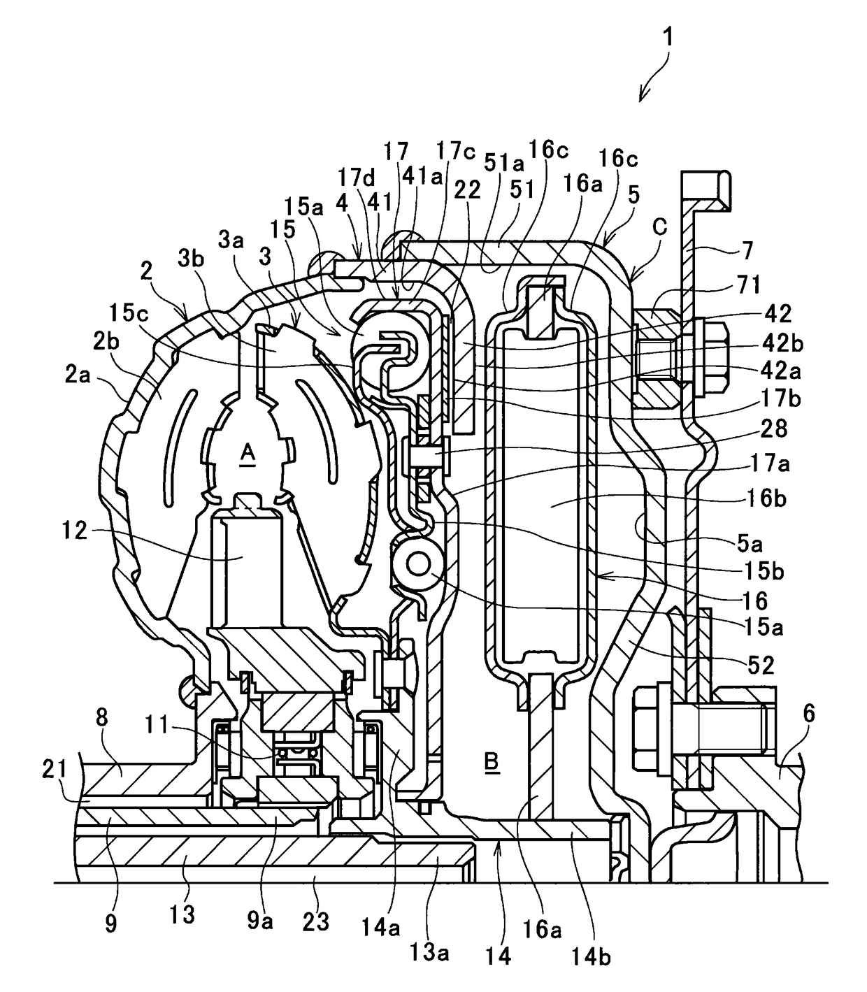
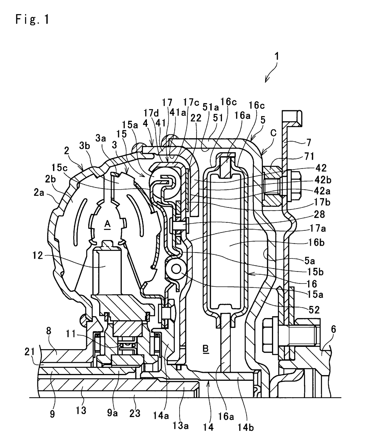
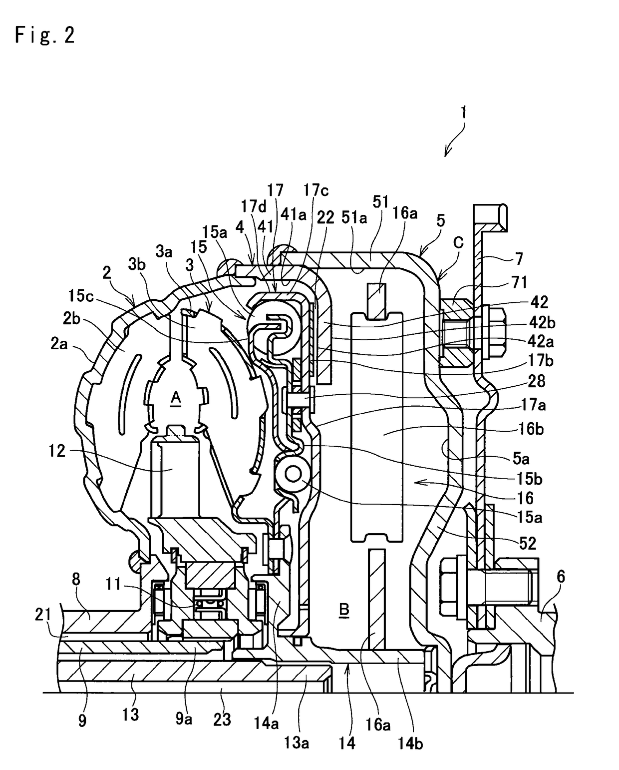
[0021]The present invention will be described more specifically below. The fluid coupling according to the present invention is a so-called torque converter having torque multiplying function and accommodating a fluid for transmitting the torque inside a cover member and including a device for damping torsional vibration. The vibration damping device includes a so-called pendulum type, and an inertial mass functioning as a weight allowed to oscillate is held by a rotary member rotated by torque, for example. Moreover, the fluid coupling has a function similar to the torque converter widely mounted on prior-art vehicles and includes a lockup clutch inside the cover member. Therefore, the present invention relates to an internal structure of the fluid coupling and particularly relates to arrangement of the torsional vibration damping device in the axial direction and the lockup clutch.

[0022]By referring to FIG. 1, the fluid coupling in one example of the present invention will be des...


PUM


Abstract

An object is to provide a fluid coupling capable of effectively utilizing an internal space of a cover member and of sufficiently exerting a performance of a device damping torsional vibration. In a fluid coupling including a cover member accommodating a fluid, a pump impeller, a turbine runner, a lockup clutch operated by a fluid pressure and selectively connecting the cover member and an output shaft, a damper mechanism having an elastic member, and a pendulum damper having a rotary member rotating integrally with the output shaft and an inertial mass capable of relative rotation with respect to the output shaft, the turbine runner, the damper mechanism, the lockup clutch, and the pendulum damper are arranged in this order in an axial direction of the output shaft inside the cover member.

Description

TECHNICAL FIELD[0001]The present invention relates to a fluid coupling provided with a device for damping torsional vibration inside a cover member.BACKGROUND ART[0002]A rotary member such as a driving shaft and a gear for transmitting a torque generated in a power source to an intended spot or member unavoidably vibrates due to fluctuation of the input torque itself, fluctuation of a load or friction. A frequency of the vibration changes in accordance with a rotation speed and since higher-mode vibration of secondary vibration or more is generated at the same time, amplitude becomes larger by resonance and hence, noise or deterioration of durability can be caused. Thus, a device or a mechanism for preventing vibration as described above is widely employed in various types of equipment for transmitting power by rotation. Particularly, a fluid coupling provided with a device for damping such torsional vibration inside a cover member is known. Examples thereof are described in Japanes...

Claims


Application Information

Patent Timeline
Patent Type & Authority Patents(United States)
IPC IPC(8): F16H45/02F16F15/14
CPCF16H45/02F16F15/145F16H2045/0278F16H2045/0226F16H2045/0263F16H2045/0205
Inventor AMANO, HIROYUKIMIYAHARA, YUAIJIMA, SHINGOYOSHINO, HIROTSUGU
Owner TOYOTA JIDOSHA KK
Why Eureka
Try Eureka