Occupancy and non-occupancy detection in the lighting system

a technology for lighting systems and occupancy and non-occupancy detection, applied in transmission, transmission, electroluminescent light sources, etc., can solve the problems of increasing the cost of dedicated sensors, reducing the effectiveness of indoors, and requiring a large amount of memory for storing data, so as to improve the effect of technology

Active Publication Date: 2018-05-29
ABL IP HLDG
View PDF3 Cites 10 Cited by
  • Summary
  • Abstract
  • Description
  • Claims
  • Application Information

AI Technical Summary

Benefits of technology

[0004]The examples disclosed herein improve over technologies for detecting one or more occupants in a space. In such examples, occupancy is sensed based on measurements of RF perturbations in an area or space. An example algorithm involves analysis of magnitude of difference from a base line and rate of change of passive RF measurements to provide occupancy sensing.

Problems solved by technology

However, many of these systems have several disadvantages.
For example, the video sensor monitoring system require a considerable amount of dedicated sensors that are expensive and require a large amount of memory for storing data.
However, such systems are generally less effective indoors or in other environments where satellite signals may be blocked, reducing accuracy of detecting the occupant in the area.
Although there have been suggestions to control lighting based on RF wireless detection results, the RF-based detection systems have not themselves been integrated as part of a lighting system of which the lighting operation are controlled as a function of the detection.

Method used


Image

  • Occupancy and non-occupancy detection in the lighting system
  • Occupancy and non-occupancy detection in the lighting system
  • Occupancy and non-occupancy detection in the lighting system

Examples


Embodiment Construction

[0028]In the following detailed description, numerous specific details are set forth by way of examples in order to provide a thorough understanding of the relevant teachings. However, it should be apparent that the present teachings may be practiced without such details. In other instances, well known methods, procedures, components, and / or circuitry have been described at a relatively high-level, without detail, in order to avoid unnecessarily obscuring aspects of the present teachings.

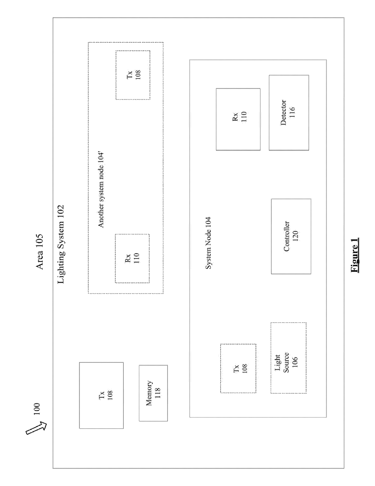
[0029]Although there have been suggestions to control lighting based on RF wireless detection results, the RF-based detection systems have not themselves been integrated as part of a lighting system of which the lighting operation are controlled as a function of the detection.

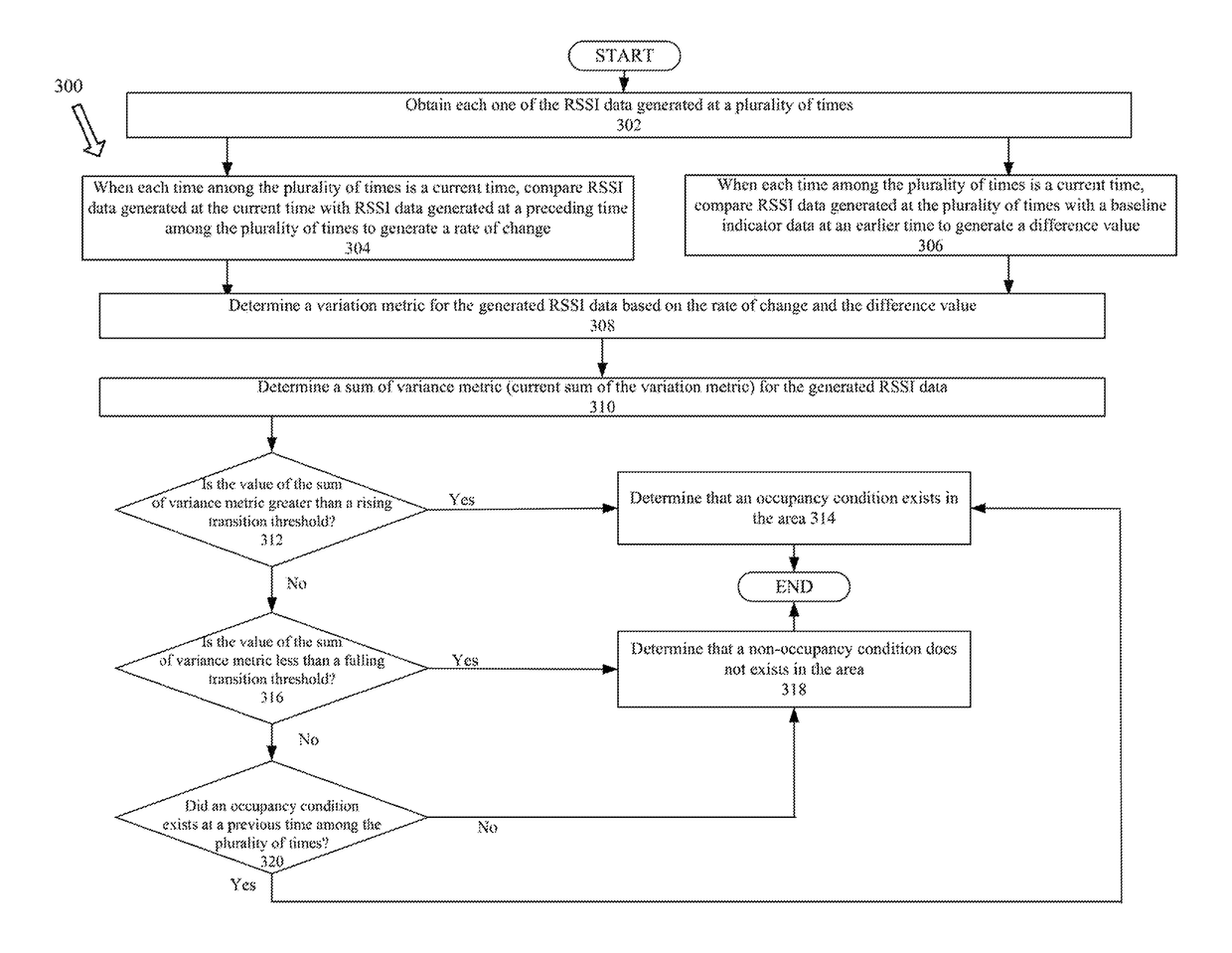
[0030]There is also room for improvement in the RF wireless detection algorithms for lighting system control. For example, an improved algorithm may enable a more rapid and real time response so that an occupant entering a prev...


PUM


Abstract

Disclosed herein is a lighting system configured to obtain an indicator data of a RF signal generated at a number of times in an area. When each such time is a current time, the indicator data generated at the current time is compared with the indicator data generated at a preceding time to determine a rate of change, and the indicator data generated at the current time is compared with a baseline indicator data at an earlier time to generate a difference value. The lighting system is configured to determine an indicator data metric based on the rate of change and the difference value and compare the indicator data metric with one of a rising transition threshold or a falling transition threshold to detect one of an occupancy condition or a non-occupancy condition in the area.

Description

BACKGROUND[0001]In recent years, a number of systems and methods have been proposed for occupancy detection within a particular area utilizing radio frequency (RF) based technologies. Examples of such systems include video sensor monitoring systems, radio frequency identification (RFID) systems, global positioning systems (GPS), and wireless communication systems among others. However, many of these systems have several disadvantages. For example, the video sensor monitoring system require a considerable amount of dedicated sensors that are expensive and require a large amount of memory for storing data. The RFID systems rely on occupants carrying an RFID tag / card that can be sensed by the RFID system to monitor the occupants. The GPS system uses orbiting satellites to communicate with the terrestrial transceiver to determine a location of the occupant in the area. However, such systems are generally less effective indoors or in other environments where satellite signals may be bloc...

Claims


Application Information

Patent Timeline
Patent Type & Authority Patents(United States)
IPC IPC(8): H05B37/00H04B17/318H05B33/08H05B37/02H05B44/00
CPCH05B37/0227H04B17/318H05B33/0845H05B37/0272H05B47/19Y02B20/40H05B47/115H05B45/10H05B47/16
Inventor MIU, MICHAELLU, MIN-HAO MICHAEL
Owner ABL IP HLDG
Why Eureka
Try Eureka