Heat exchanger

a heat exchanger and heat exchanger technology, applied in indirect heat exchangers, lighting and heating apparatus, transportation and packaging, etc., can solve the problems of affecting the discharge performance of melted water defrosted by the first heat exchanger, the insufficient consideration of the inability to adequately consider the collection/distribution of first fluid from the first tube, etc., to achieve the effect of improving the draining performance of melted water defro

Inactive Publication Date: 2018-06-12
DENSO CORP
View PDF40 Cites 6 Cited by
  • Summary
  • Abstract
  • Description
  • Claims
  • Application Information

AI Technical Summary

Benefits of technology

[0013]With the above configuration, the heat transfer from the second fluid toward the outer wall of the tank unit can be improved to further promote the defrosting of the tank unit.
[0048]According to the above configuration, since the notches or recesses formed in the outer wall of the tank unit function as the drain ditches, the drainage performance of the melted water defrosted by the first heat exchanger can be improved.

Problems solved by technology

According to the present inventors' study, in the conventional art, attention is paid to melt frost generated in the vicinity of an outer surface of first tubes (refrigerant tubes), but frost generated on outer surfaces of collection / distribution tank units (refrigerant tanks) for distributing a first fluid (refrigerant) to the first tubes, or collecting the first fluid from the first tubes may not be sufficiently considered.
The frost thus generated on the outer surface of the tank units not only causes the discharge of melted water obtained by melting the frost generated on the outer surface of the tubes to be blocked, but also may cause the melted water to be refrozen.

Method used


Image

  • Heat exchanger
  • Heat exchanger
  • Heat exchanger

Examples


first embodiment

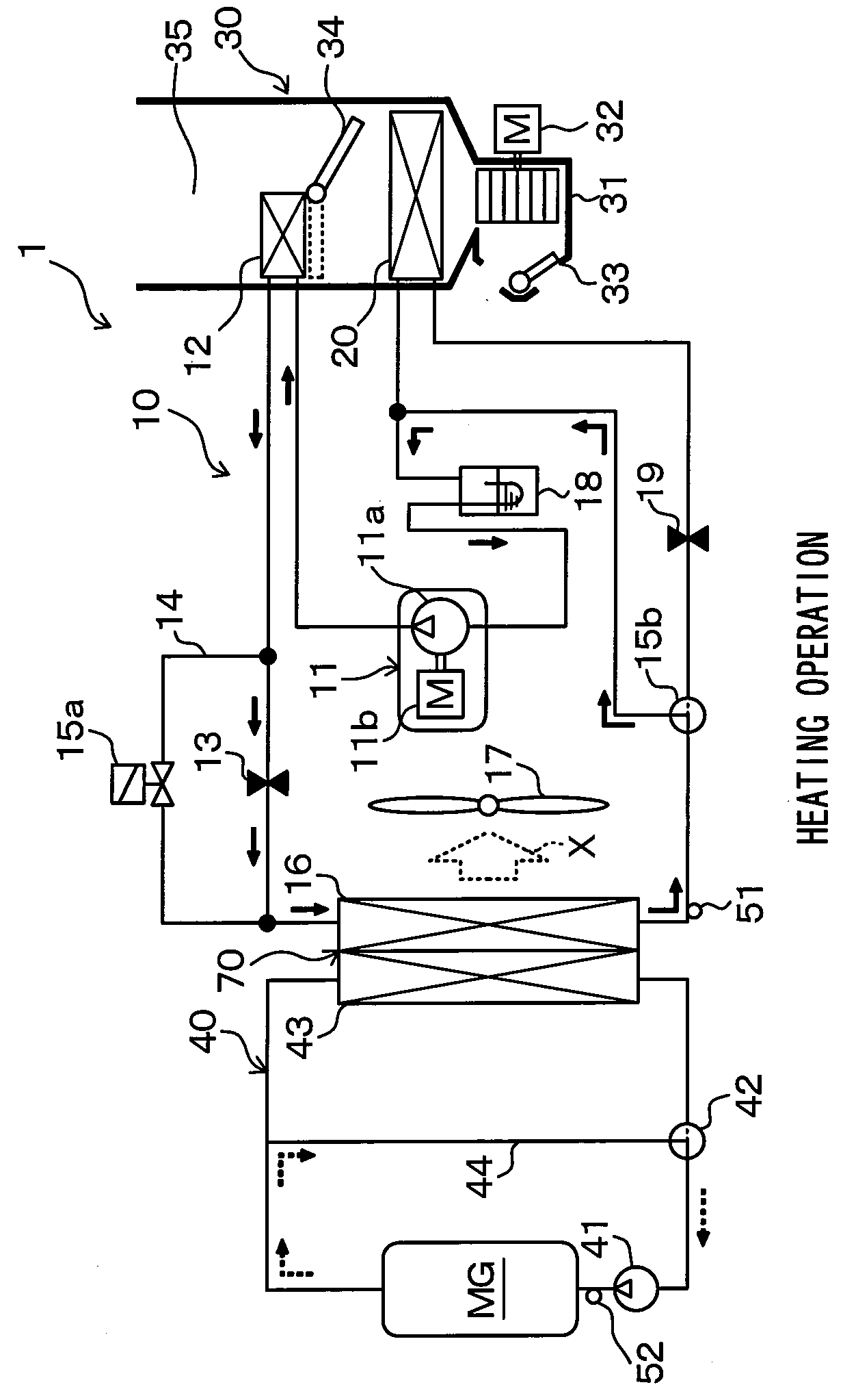
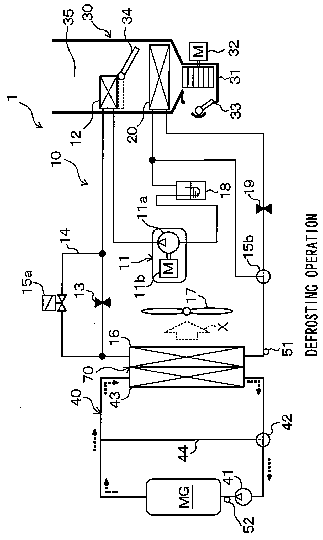
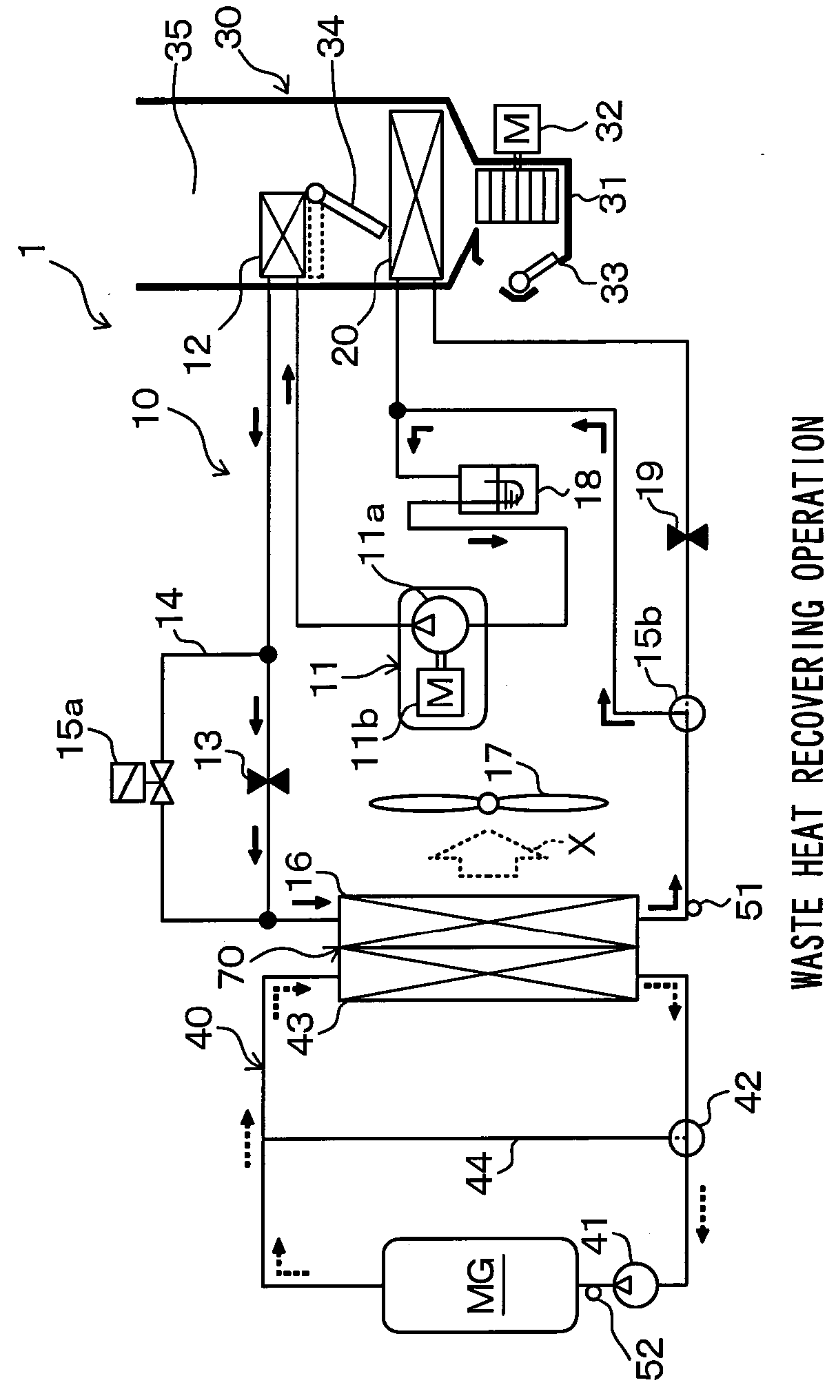
[0079]A first embodiment will be described with reference to FIGS. 1 to 8. In this embodiment, a heat exchanger 70 according to the present disclosure is applied to a heat pump cycle 10 that regulates a temperature of a vehicle interior blowing air in a vehicle air conditioner 1. FIGS. 1 to 4 are diagrams illustrating an overall configuration of the vehicle air conditioner 1 according to this embodiment. The vehicle air conditioner 1 is applied to a so-called hybrid electric vehicle that obtains a drive force for vehicle travel from an internal combustion engine (engine) and a travel electric motor MG.

[0080]The hybrid electric vehicle runs or stops the engine according to a travel load of the vehicle, and can switch between a travel state in which the vehicle obtains the drive force from both the engine and the travel electric motor MG, and a travel state in which the vehicle stops the engine and obtains the drive force from only the travel electric motor MG to travel. With the abov...

second embodiment

[0224]In this embodiment, the refrigerant side intermediate plate member 162 is formed by stacking multiple plate members.

[0225]The detailed configuration of the heat exchanger 70 according to this embodiment will be described with reference to FIG. 9. FIG. 9(a) is a cross-sectional view of the heat exchanger 70, which corresponds to FIG. 7(b) of the first embodiment. FIG. 9(b) is a cross-sectional view of the heat exchanger 70, which corresponds to FIG. 7(c) of the first embodiment. In FIG. 9, parts identical with or equivalent to those in the first embodiment are denoted by the same symbols. The same is applied to the following drawings.

[0226]The refrigerant side intermediate plate member 162 is formed by stacking two plate members of a communication space formation plate member 801 and a partition plate member 802 on each other. The communication space formation plate member 801 is arranged on the coolant tubes 43a side (upper side of FIG. 9), and the partition plate member 802 i...

third embodiment

[0237]In this embodiment, as illustrated in FIGS. 10 and 11, drain ditches for improving a drainage performance of the melted water defrosted by the vehicle exterior heat exchange unit 16 are formed in side surfaces of the refrigerant side tank unit16c.

[0238]FIG. 10 is a cross-sectional view of the tank unit 16c according to this embodiment. FIG. 11(a) is an exploded view of the tank unit 16c according to this embodiment, and FIG. 11(b) is a perspective view of the tank unit 16c according to this embodiment.

[0239]As described above, the refrigerant side tank unit 16c includes the refrigerant side fixing plate member 161 (outer wall component) to which both the refrigerant tubes 16a and the coolant tubes 43a are fixed, the refrigerant side intermediate plate member 162 (intermediate plate member) fixed to the refrigerant side fixing plate member 161, and a refrigerant side tank formation member 163 (outer wall component).

[0240]The refrigerant side tank formation member 163 is fixed ...


PUM


Abstract

In a heat exchanger, a second fluid flowing space communicating with second tubes is formed to be divided from a first tank space within a tank unit forming a first tank space that collects or distributes a refrigerant. The tank unit is defrosted by a coolant flowing in the second fluid flowing space, which is higher in temperature than the refrigerant flowing in the first tank space. With this configuration, heat from the second fluid flowing in the second fluid flowing space included in the tank unit is effectively transferred to a portion of the tank unit which is likely to be frosted.

Description

CROSS REFERENCE TO RELATED APPLICATIONS[0001]This application is a U.S. National Phase Application under 35 U.S.C. 371 of International Application No. PCT / JP2012 / 007625, filed on Nov. 28, 2012 and published in Japanese as WO / 2013 / 080532 A1 on Jun. 6, 2013. This application is based on Japanese Patent Applications No. 2011-260522 filed on Nov. 29, 2011, and No. 2012-250501 filed on Nov. 14, 2012. The disclosures of all of the above applications are incorporated herein by reference.TECHNICAL FIELD[0002]The present disclosure relates to a combined heat exchanger configured to enable heat exchange among three types of fluids.BACKGROUND ART[0003]Conventionally, a combined heat exchanger configured to enable heat exchange among three types of fluids has been known. For example, a heat exchanger disclosed in Patent Document 1 is a combined heat exchanger configured to enable both heat exchange between a refrigerant of a refrigeration cycle device and a vehicle exterior air (outside air) a...

Claims


Application Information

Patent Timeline
Patent Type & Authority Patents(United States)
IPC IPC(8): F28D1/04B60H1/00F28D1/053F28D1/02F28F9/02
CPCF28D1/0408B60H1/00328B60H1/00921F28F9/0278F28D1/0452F28D1/05391F28D1/0246
Inventor KATOH, YOSHIKI
Owner DENSO CORP
Why Eureka
Try Eureka