Atmospheric temperature detecting apparatus and exhaust emission purification apparatus

a technology of atmospheric temperature and airflow sensor, which is applied in the direction of machines/engines, electric control, instruments, etc., can solve problems such as dynamic temperature error calculation, and achieve the effect of greatly improving the accuracy of atmospheric temperature detection by airflow sensor

Inactive Publication Date: 2010-10-12
NISSAN DIESEL MOTOR CO
View PDF7 Cites 5 Cited by
  • Summary
  • Abstract
  • Description
  • Claims
  • Application Information

AI Technical Summary

Benefits of technology

[0010]Therefore, in view of the above-described problems encountered by the conventional techniques, the present invention has an object to provide an atmospheric temperature detecting apparatus capable of realizing an improvement of accuracy in the detection of the atmospheric temperature by compensating a temperature signal output by a hot wire airflow sensor in accordance with the engine operating state.
[0014]In the atmospheric temperature detecting apparatus according to the present invention, an intake air temperature detected by the airflow sensor is corrected in accordance with the engine operating state, so that the atmospheric temperature can be estimated. Specifically, since the airflow sensor is disposed near the engine, there is a possibility that the airflow sensor is thermally influenced by combustion heat of an air-fuel mixture, so that the intake air temperature detected by the airflow sensor becomes different from an actual temperature. However, due to correction of the intake air temperature in accordance with the engine operating state, it is able to cancel out the influence of the combustion heat, and the accuracy of detecting the atmospheric temperature by the airflow sensor can be greatly improved.
[0015]With the exhaust emission purification apparatus according to the present invention, it is possible to avoid such various inconveniences in electric heater control that either the electric heater is operated even when a reducing agent or its precursor is not frozen or the electric heater is not brought into operation in spite of the fact that the reducing agent or its precursor is frozen. Consequently, prevention of freezing the reducing agent or its precursor and promotion of defrosting of the reducing agent or its precursor can be properly achieved.

Problems solved by technology

Further, the dynamic temperature error is calculated by correcting a steady temperature error with a smoothed time constant of the temperature change.

Method used


Image

  • Atmospheric temperature detecting apparatus and exhaust emission purification apparatus
  • Atmospheric temperature detecting apparatus and exhaust emission purification apparatus
  • Atmospheric temperature detecting apparatus and exhaust emission purification apparatus

Examples


Embodiment Construction

[0021]Hereunder is a detailed description of the present invention with reference to the accompanying drawings.

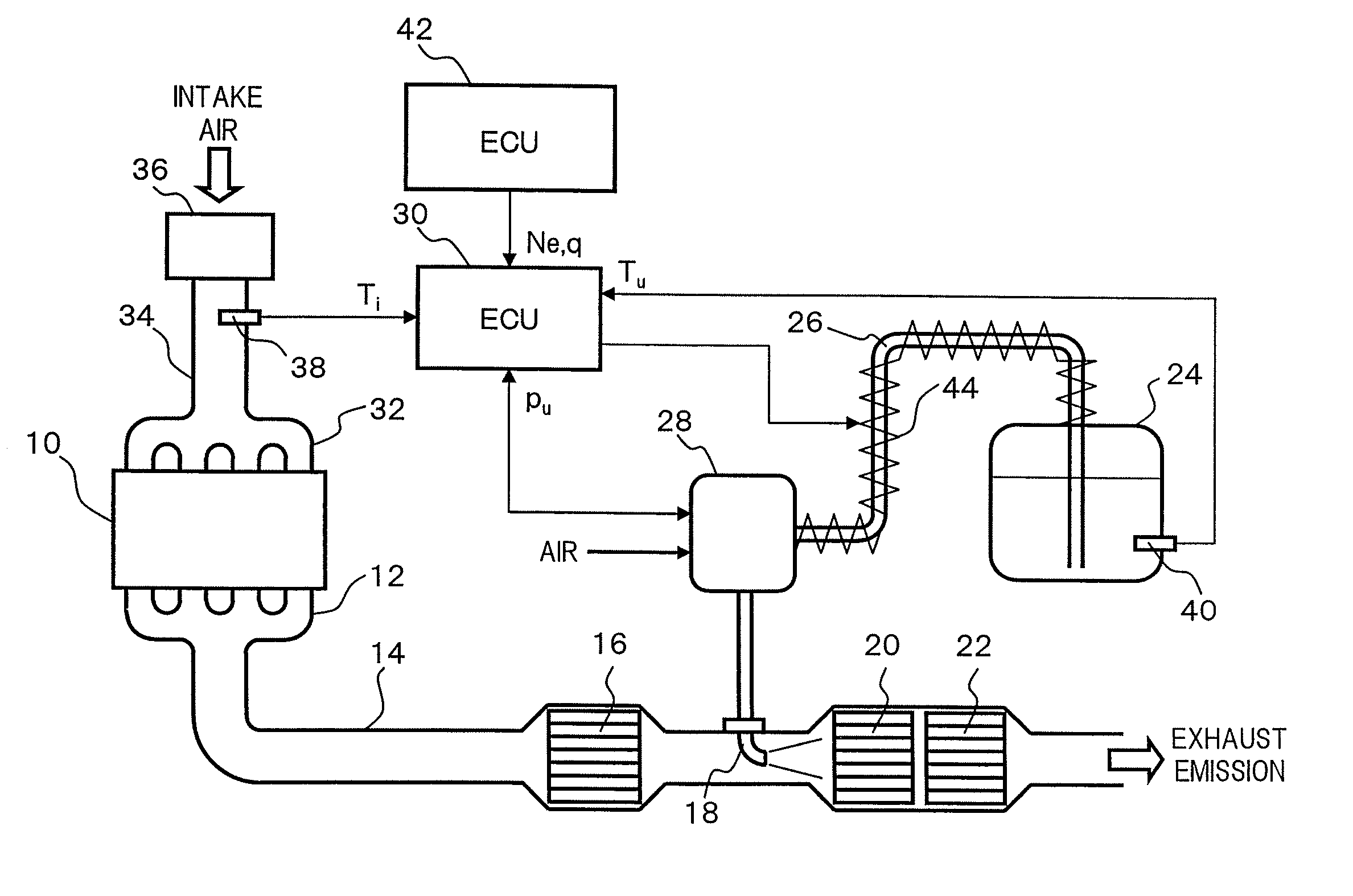
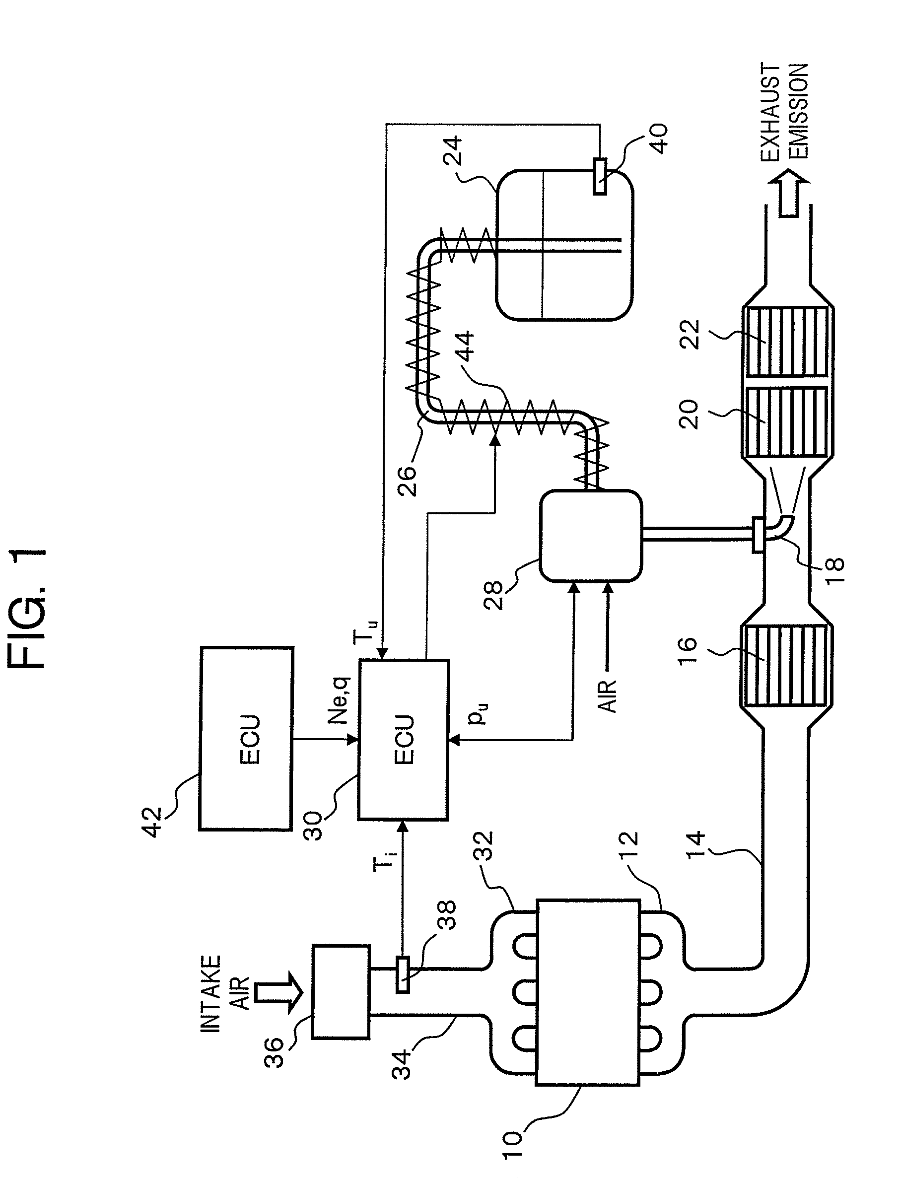
[0022]FIG. 1 shows a general configuration of an exhaust emission purification apparatus provided with an atmospheric temperature detecting apparatus according to the present invention.

[0023]In an exhaust pipe 14 connected to an exhaust manifold 12 of an engine 10, a nitrogen oxidation catalytic converter 16 for oxidizing nitric oxide (NO) to nitrogen dioxide (NO2), an injection nozzle 18 for injecting and supplying urea aqueous solution as a reducing agent precursor, an NOx reduction catalytic converter 20 for reducing NOx by using ammonia obtained from the urea aqueous solution as a reducing agent, and an ammonia oxidation catalytic converter 22 for oxidizing ammonia passed through the NOx reduction catalytic converter 20 are disposed along flow direction of the exhaust emission. The urea aqueous solution stored in a reducing agent container 24 is supplied to a reducing a...


PUM


Abstract

An intake air temperature detected by an airflow sensor is corrected based on a rotation speed of an engine and a fuel supply amount to thereby estimate an atmospheric temperature. The atmospheric temperature is estimated by calculating a dynamic temperature error caused by heat generated around an engine and a correction factor in regard to thermal influence which changes according to the flow rate of an intake air, and correcting the intake air temperature detected by the airflow sensor with the temperature error corrected with the correction factor. On the basis of the atmospheric temperature, an electric heater is controlled, which is provided on at least a part of a system of supplying a reducing agent or its precursor, for example, a supply pipe mutually communicating a reducing agent container with a reducing agent supplying apparatus.

Description

[0001]This application is a continuation of PCT / JP2006 / 322352, filed on Nov. 9, 2006.BACKGROUND OF THE INVENTION[0002]1. Field of Invention[0003]The present invention relates to a technique of detecting atmospheric temperature at high accuracy by using a hot wire airflow sensor. The present invention also relates to a technique of controlling an electric heater provided in a system of supplying a reducing agent or its precursor at high accuracy in response to atmospheric temperature in an exhaust emission purification apparatus which is provided for reducing nitrogen oxide (NOx) in exhaust emission from an engine by using the reducing agent.[0004]2. Description of the Related Art[0005]As a catalytic purification system for reducing NOx in engine exhaust emission, an exhaust emission purification apparatus described in Japanese Laid-Open (Kokai) Patent Application Publication No. 2000-27627 has been proposed. In such an exhaust emission purification apparatus, a reducing agent or its...

Claims


Application Information

Patent Timeline
Patent Type & Authority Patents(United States)
IPC IPC(8): F01N3/10
CPCF01N3/208F02D41/187F01N13/009F01N2610/02F01N2610/10F02D2200/0414F02D2200/0416Y02T10/24Y02T10/12
Inventor MATSUNAGA, HIDEKI
Owner NISSAN DIESEL MOTOR CO
Why Eureka
Try Eureka