Construction Machine

a construction machine and connector technology, applied in the direction of machines/engines, mechanical equipment, transportation and packaging, etc., can solve the problems of affecting the operation of the construction machine, the difference of elevation between and the discharge pressure of the urea water supply device to the urea water injection valve could vary significantly, so as to achieve the effect of effective use of the connection frame, favorable warming, and promotion of defrosting of ur

Inactive Publication Date: 2015-09-17
NIHON KENKI CO LTD
View PDF24 Cites 4 Cited by
  • Summary
  • Abstract
  • Description
  • Claims
  • Application Information

AI Technical Summary

Benefits of technology

[0019]The present invention is made in the light of the problem as above, and has an object to provide a construction machine which is designed so that a urea water supply system can be installed efficiently with urea water made always injectable stably from a urea water injection valve, and a thermal insulating cover that keeps a connector portion of urea water supply piping of the urea water supply device of the urea water supply system warm can be efficiently mounted.
[0022]Accordingly, even when the construction machine significantly tilts with the front side lowered in the longitudinal direction, a change of the distance in the vertical direction from the urea water tank to the urea water supply device is restrained to be small, and urea water sucking performance of the urea water supply device from the urea water tank can be favorably ensured with a slight variation. Likewise, a change of the distance in the vertical direction from the urea water supply device to the urea water injection valve is also restrained to be small, and the urea water discharge pressure of the urea water supply device to the urea water injection valve can be also favorably ensured with a slight variation.
[0023]At this time, the urea water supply device is provided at the existing connection frame, and therefore, the urea water supply device can be installed by effectively using the connection frame, without providing a mounting bracket additionally.
[0024]Further, since the urea water supply device is provided to face the engine, the urea water supply device is favorably warmed by the heat of the engine, and even in the winter season, freezing of the urea water flowing in the urea water supply device can be prevented while defrost of the urea water which is frozen can be promoted.

Problems solved by technology

However, the urea water supply piping and the cooling water piping are connected to the urea water tank and the urea water supply device by using connectors, and the cooling water piping cannot be laid along the urea water supply piping at the connector portions, whereby there arises the problem that urea water is easily frozen at the connector portion.
When the urea water supply device is placed on the urea water tank like this, the length of the piping from the urea water supply device to the urea water injection valve is long, and when the construction machine tilts in the longitudinal direction, the difference of elevation between the urea water supply device and the urea water injection valve significantly changes, and the discharge pressure of the urea water supply device to the urea water injection valve could vary significantly, whereby there arises the problem of being unable to inject the urea water stably.
However, when the thermal insulating cover is provided at the urea water supply device, it becomes the problem how the urea water supply device is installed on the revolving superstructure with easiness in attaching and detaching work of the thermal insulating cover as well as the above described maintenance workability, and how efficiently the thermal insulating cover is mounted to the urea water supply device.

Method used


Image

  • Construction Machine
  • Construction Machine
  • Construction Machine

Examples


Embodiment Construction

[0038]Hereinafter, one embodiment of a construction machine according to the present invention will be described based on the drawings.

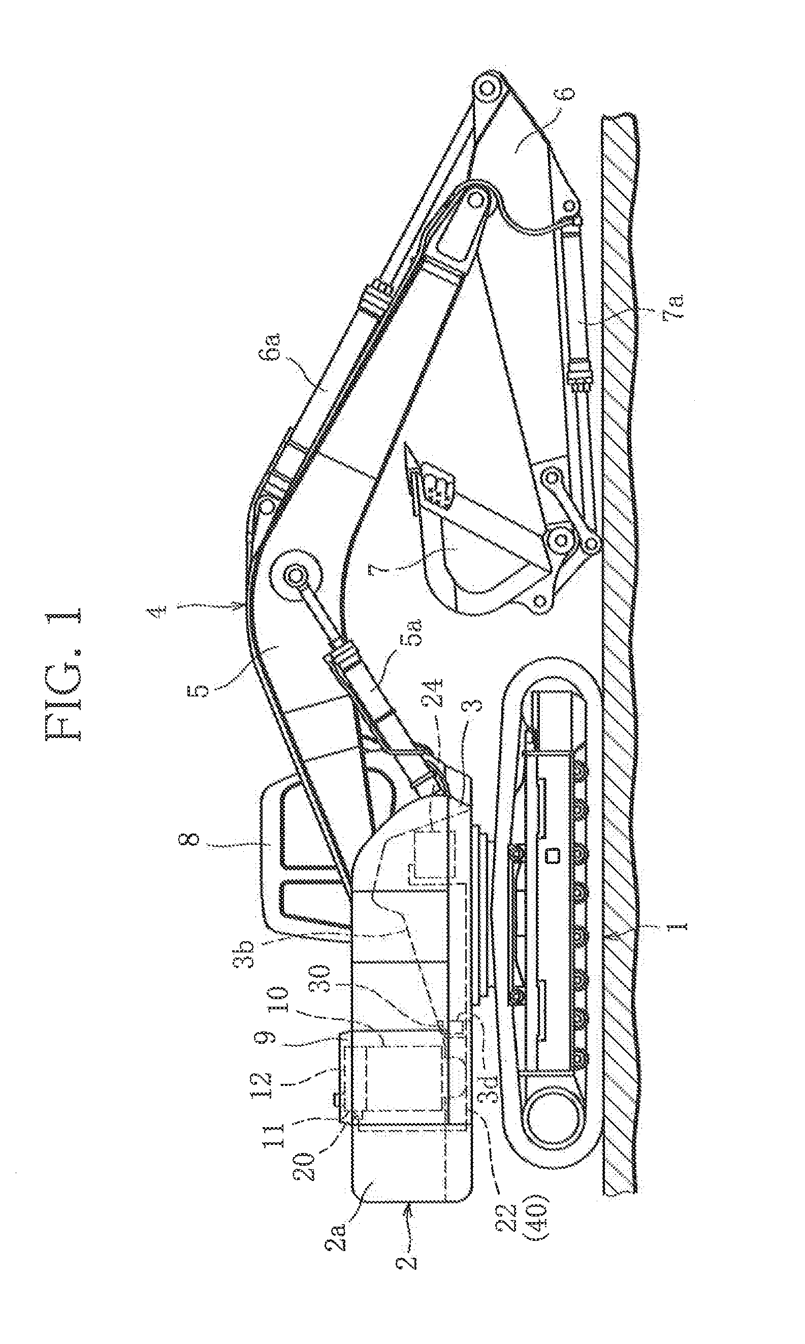
[0039]FIG. 1 shows the construction machine including a urea water supply system according to the present invention. In the present embodiment, as the construction machine, a crawler type hydraulic shovel will be described by being cited as an example.

[0040]As shown in FIG. 1, the hydraulic shovel is constructed by including a traveling structure 1, a revolving superstructure 2 that is disposed on the traveling structure 1 and is mainly constituted of a revolving frame 3, and a working device 4 that is mounted to the revolving superstructure 2 and performs excavating work of earth and sand, and the like.

[0041]The working device 4 is constructed by including a boom 5 that is mounted to the revolving frame 3 rotatably in a vertical direction, an arm 6 that is mounted to a tip end of the boom 5 rotatably in the vertical direction, and a bucket 7 that is...


PUM


Abstract

In a NOx selective catalytic reduction device that purifies NOx in exhaust gas exhausted from an engine, a urea water supply system is constructed of a urea water injection valve, a urea water tank, urea water supply piping and a urea water supply device, a connection frame member is provided on a revolving superstructure to extend in a longitudinal direction in a center in a width direction to reinforce the revolving superstructure and to be located between a pair of main frame members that connects a working device so that a rear side faces the engine, the urea water tank is placed on the revolving superstructure on a front side from a center of revolution of the revolving superstructure, the engine is placed on the revolving superstructure on a rear side from the center of revolution of the revolving superstructure, and the urea water supply device is installed on the connection frame member to face the engine.

Description

BACKGROUND OF THE INVENTION[0001]1. Field of the Invention[0002]The present invention relates to a construction machine, and particularly relates to an installation structure of a urea water supply device that feeds urea water under pressure to a urea water injection valve in a urea water supply system of an engine that is mounted on a construction machine.[0003]2. Description of the Related Art[0004]A construction machine such as a hydraulic shovel is constructed by including a traveling structure capable of travelling by a traveling motor, a revolving superstructure that is disposed on the traveling structure, and a working device that is mounted to the revolving superstructure to perform an excavating work of earth and sand, or the like. The revolving superstructure has an operator's cab thereon located on one side in a width direction with a mounting section for the working device between both sides. Such a construction machine further has a hydraulic pump that is located on a r...

Claims


Application Information

Patent Timeline
Patent Type & Authority Applications(United States)
IPC IPC(8): E02F9/08E02F9/18E02F9/16
CPCE02F9/0875E02F9/0866E02F9/18E02F9/0883E02F9/16B60K13/04B60Y2200/412E02F9/0808E02F9/0833F01N3/2066F01N2610/02F01N2610/1406Y02A50/20
Inventor FUJII, TOSHINORIMANO, HIDENORIKAMIYA, SHOHEI
Owner NIHON KENKI CO LTD
Why Eureka
Try Eureka