Oil separator

a technology of oil separator and separator chamber, which is applied in the direction of separation process, machine/engine, vortex flow apparatus, etc., can solve the problems of blow-by gas including such an oil mist flowing back, and not all the mixed gas introduced to the combustion chamber is burned

Inactive Publication Date: 2015-10-22
AISIN SEIKI KK
View PDF5 Cites 8 Cited by
  • Summary
  • Abstract
  • Description
  • Claims
  • Application Information

AI Technical Summary

Problems solved by technology

However, not all the mixed gas introduced to the combustion chamber is burnt.
It is undesired that the blow-by gas including such an o

Method used


Image

  • Oil separator
  • Oil separator
  • Oil separator

Examples


first embodiment

[0025]1. First Embodiment

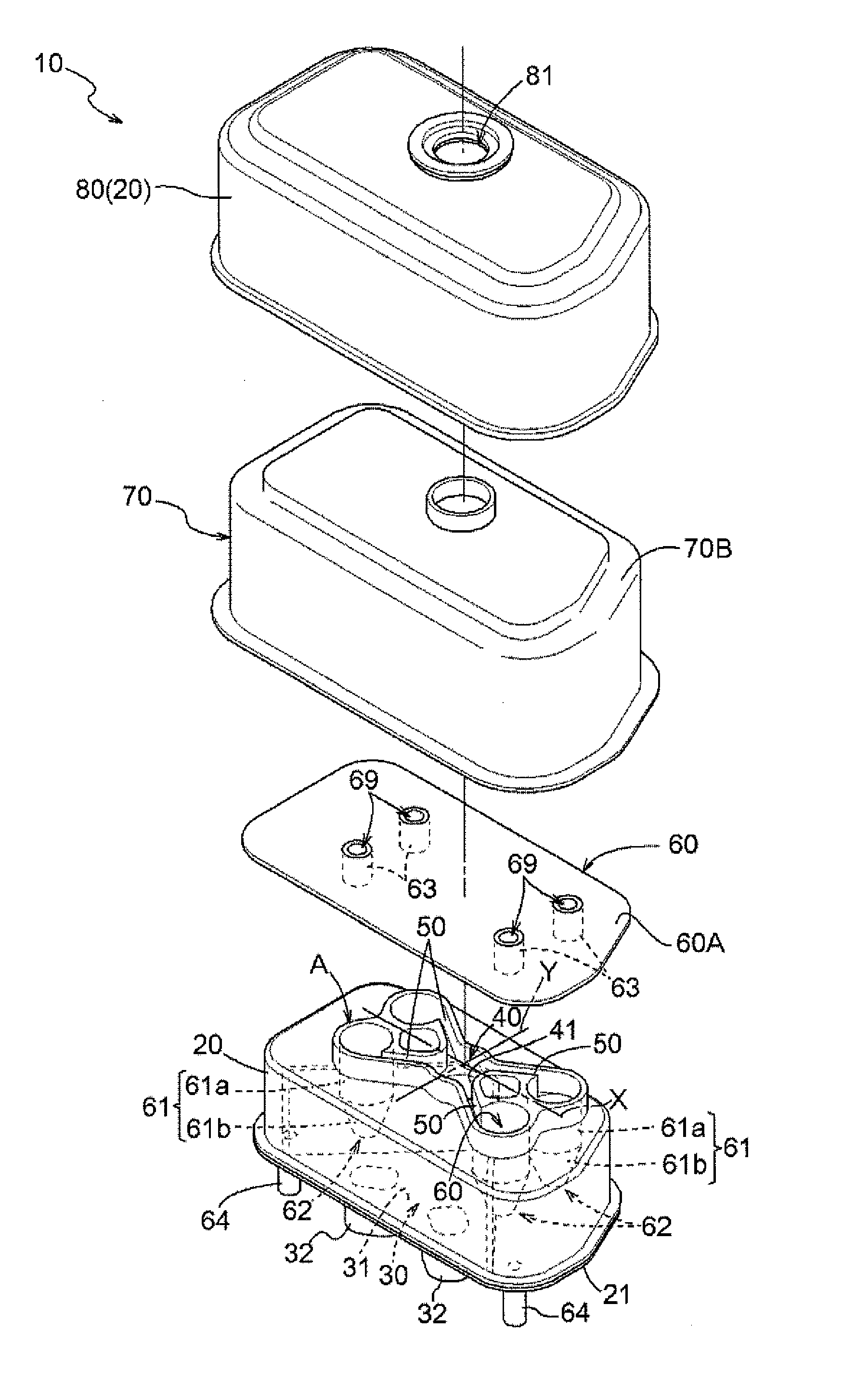
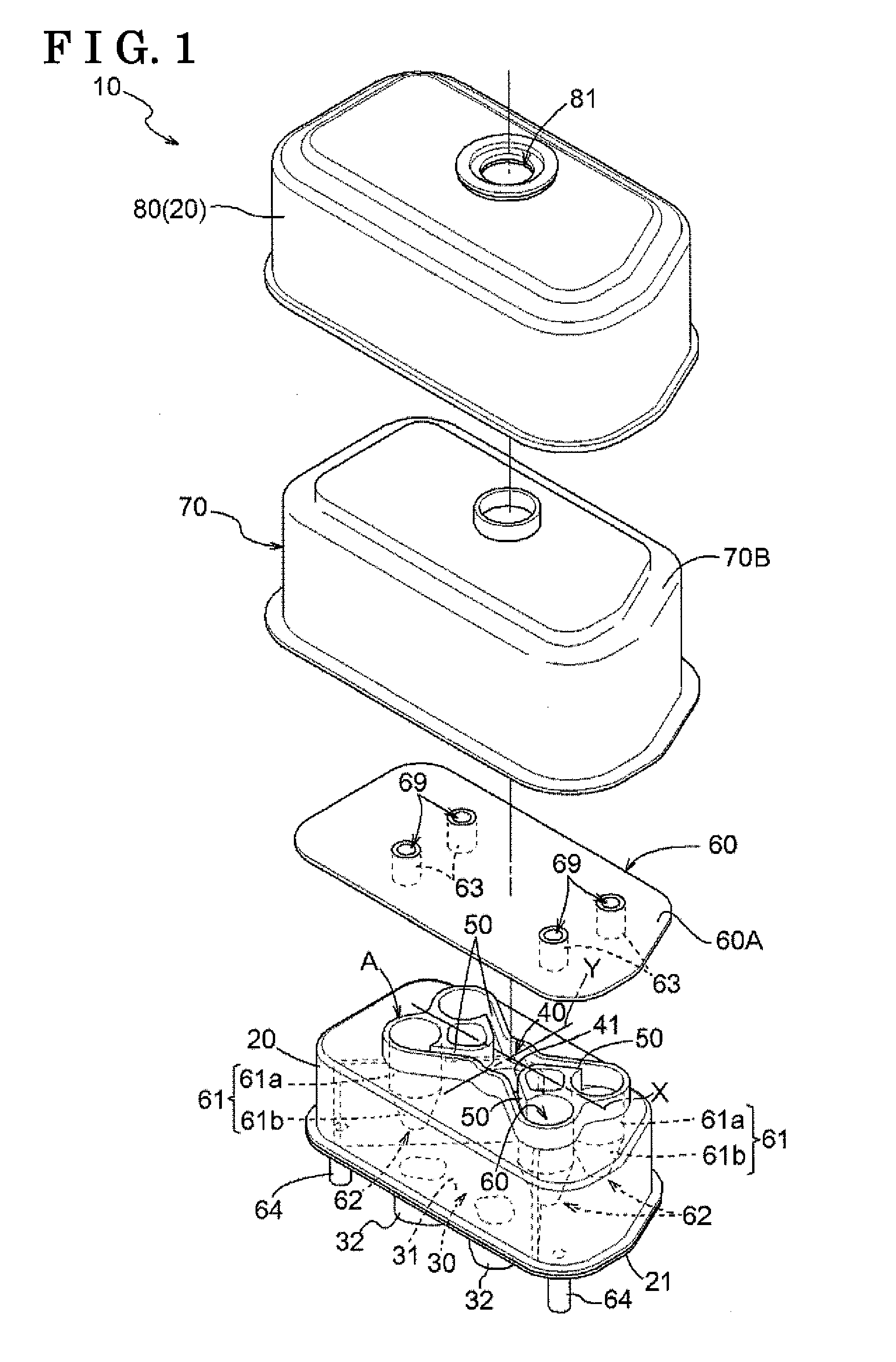
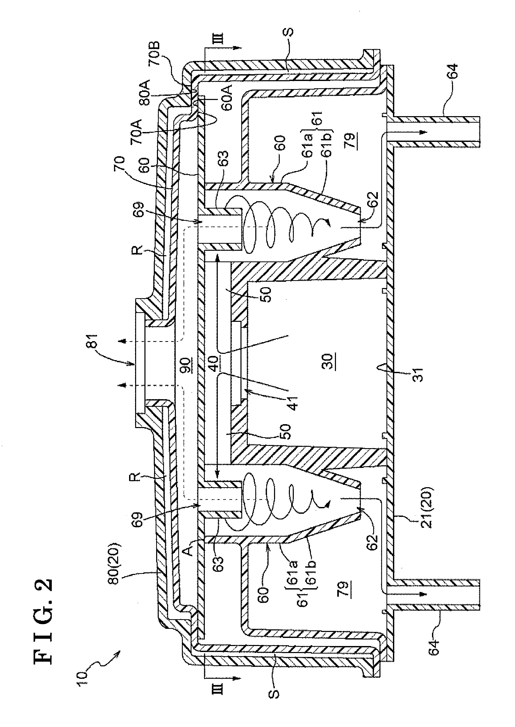
[0026]An oil separator related to the present invention is provided with a function of reducing influence of outside air so that the oil separator is easily warmed up at start-up of an engine. The oil separator related to the present embodiment will be described hereunder with reference to the drawings. FIG. 1 is an exploded perspective view illustrating an external appearance of an oil separator 10 related to the present embodiment. FIG. 2 is a lateral cross-sectional view of the oil separator 10. FIG. 3 is a cross-sectional view taken along line III-III in FIG. 2. FIG. 4 is a cross-sectional view taken along line IV-IV in FIG. 3. The oil separator 10 is made of resin and is arranged inside a head cover of the engine of a vehicle (not shown).

[0027]As illustrated in FIG. 1 and FIG. 2, the oil separator 10 is provided with a housing 20 constituting an outer wall, a first storage chamber 30 formed inside the housing 20, a gas introduction pipe 32, a distributi...

second embodiment

[0051]2. Second Embodiment

[0052]Next, the second embodiment of the oil separator 10 will be described. A lateral cross-sectional view of the oil separator 10 related to the second embodiment is illustrated in FIG. 5. The present embodiment differs from the first embodiment in that the inflow port 41 is formed at an end portion of the housing 20 and that the axis centers of the four oil separation units 60 are arranged in a line on the plane surface X. Further, an aspect that the gas discharge hole 81 is provided at an end portion of the oil separator 10 is also different from the first embodiment. By arranging the four oil separation units 60 in a line in such a manner that the four axis centers are on the plane surface X, a thickness of the oil separator 10 in the direction orthogonal to the plane surface X can be even thinner compared to the first embodiment.

[0053]In addition, also in the present embodiment, by the first cover portion 70 and the second cover portion 80, the upper ...


PUM

PropertyMeasurementUnit
Heataaaaaaaaaa

Abstract

An oil separator includes at least one set of cyclone-type oil separation unit performing gas-liquid separation of blow-by gas, a distribution chamber distributing the blow-by gas flowing into the oil separation unit, an inflow port causing the blow-by gas to flow into the distribution chamber, a branch passage causing the blow-by gas to flow from the distribution chamber to each oil separation unit individually, a first cover portion placed over the oil separation unit to include therewithin the distribution chamber, the inflow port and the branch passage and to enclose the distribution chamber, the inflow port and the branch passage, and a second cover portion including therewithin the first cover portion and enclosing the first cover portion, wherein part of at least an upper surface portion of the oil separator is formed in a two-layer structure by the first cover portion and the second cover portion.

Description

TECHNICAL FIELD[0001]The present invention relates to an oil separator separating oil mist from blow-by gas.BACKGROUND ART[0002]An engine obtains motive power by burning mixed gas in a combustion chamber, thereby rotating a crankshaft. However, not all the mixed gas introduced to the combustion chamber is burnt. Part of the mixed gas leaks out to a crankcase from a gap between a piston and a cylinder. The gas that has leaked is referred to as blow-by gas. The blow-by gas is unburnt gas and discharging as is to the atmosphere as exhaust gas is prohibited by law. Therefore, the blow-by gas is configured to flow back to an intake port-side again via a PCV (Positive Crankcase Ventilation) passage, be burnt in the combustion chamber together with new mixed gas, and then be discharged to the atmosphere.[0003]In the blow-by gas, lubrication oil such as engine oil exists as oil mist. It is undesired that the blow-by gas including such an oil mist is flowed back to an intake port because the...

Claims


Application Information

Patent Timeline
IPC IPC(8): F01M13/04B01D45/16
CPCF01M13/04F01M2013/0427B01D45/16B04C5/04B04C5/28F01M13/0416F01M2013/0066
Inventor KIRA, NAOKINISHIGAKI, ATSUSHI
Owner AISIN SEIKI KK
Why Eureka
Try Eureka