

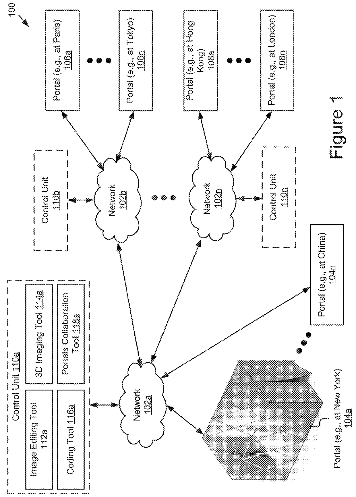
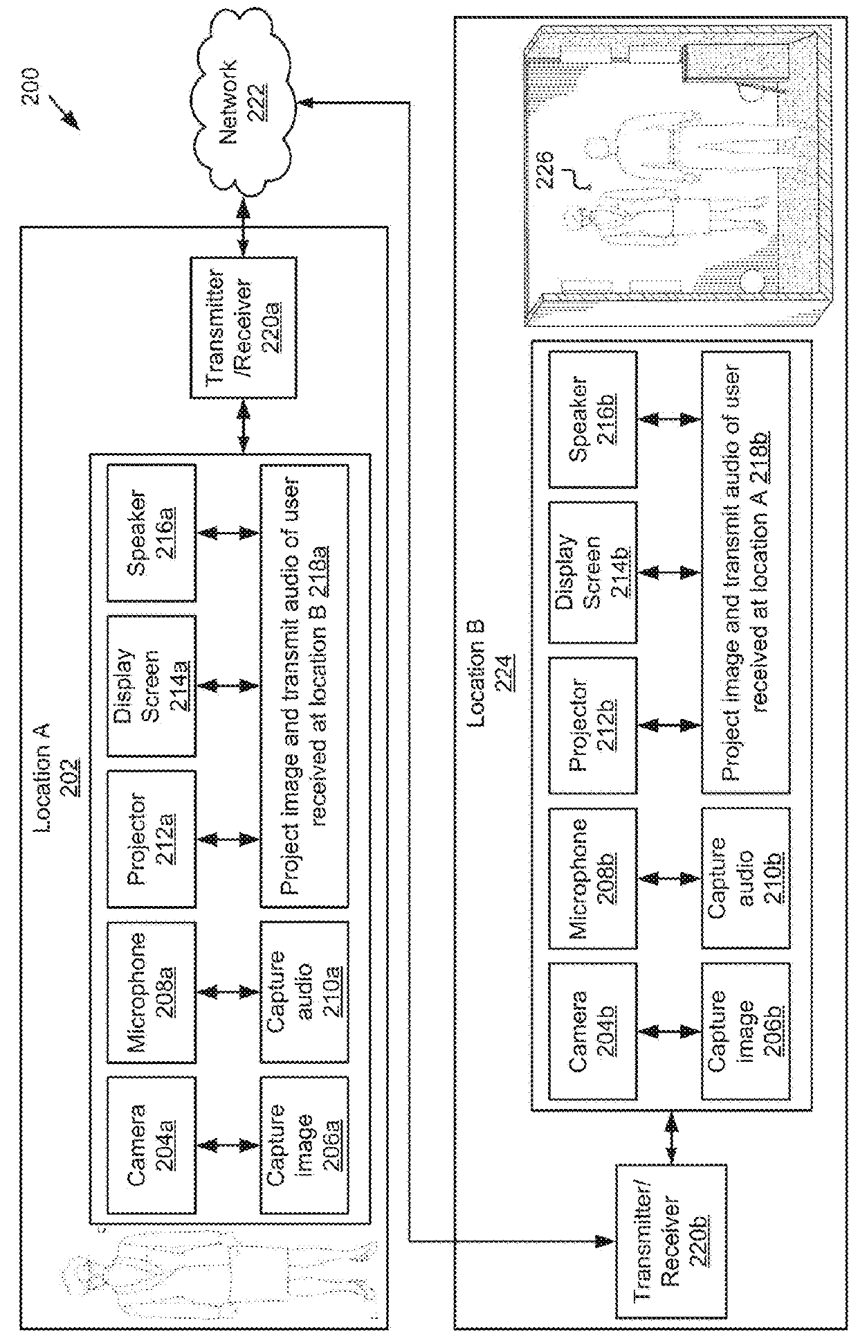
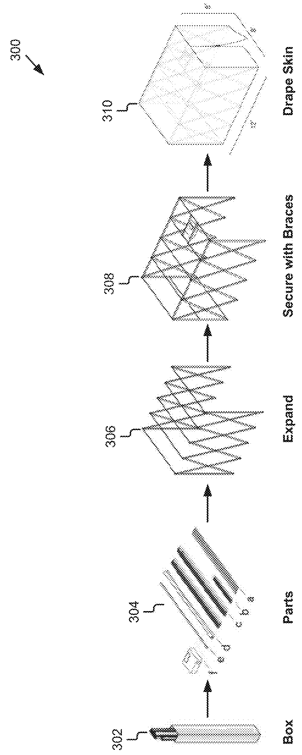
Network architecture for immersive audio-visual communications by temporary communication structures
a technology of audio-visual communication and communication structure, applied in the field of network architecture for immersive audio-visual communication by temporary communication structure, can solve the problems of limited technological access available to many people in remote locations, mediocre recording, transmission and presentation quality and capabilities through standard laptop or computer screen, and many communities in the world simply do not have easy access to computing power, audio-video tools, electricity sources, and communication. , to achieve the effect of enhancing immersive audio-visual communication and facilitating viewing of landscap
- Summary
- Abstract
- Description
- Claims
- Application Information
AI Technical Summary
Benefits of technology
Problems solved by technology
Method used
Image

Examples
Embodiment Construction
[0041]Embodiments of the present invention will now be described in detail with reference to the drawings, which are provided as illustrative examples so as to enable those skilled in the art to practice the invention. Notably, the figures and examples below are not meant to limit the scope of the present invention to a single embodiment, but other embodiments are possible by way of interchange of some or all of the described or illustrated elements. Wherever convenient, the same reference numbers will be used throughout the drawings to refer to same or like parts. Where certain elements of these embodiments can be partially or fully implemented using known components, only those portions of such known components that are necessary for an understanding of the present invention will be described, and detailed descriptions of other portions of such known components will be omitted so as not to obscure the invention. In the present specification, an embodiment showing a singular compon...
PUM
 Abstract
Description
Claims
Application Information