Some uses of microencapsulation for electric paper

a technology of microencapsulation and electric paper, which is applied in the field of some uses of microencapsulation for electric paper, can solve the problems of affecting the appearance, the final product lacks some of the optical and tactile properties of paper, and the gel is soft and lacks durability, so as to achieve convenient conformation and greater flexibility of applications.

Inactive Publication Date: 2001-03-06
XEROX CORP
View PDF10 Cites 26 Cited by
  • Summary
  • Abstract
  • Description
  • Claims
  • Application Information

AI Technical Summary

Benefits of technology

The bichromal balls are individually enclosed in spherical shells with the space between the two spherical surfaces filled with dielectric liquid. The resultant capsules may be dispersed in a second liquid, such as an optically clear epoxy, which may be subsequently hardened. If the hardened liquid, now a solid, is of sufficient strength no further protection is required. The resultant display is then in the form of a thin, paper-like sheet without the bulkiness and optical problems created by the protective cover sheets as in the prior art. Alternatively, the resultant display may be easily conformally coated on a non-planar surface for even greater flexibility of applications.

Problems solved by technology

After being soaked in plasticizer, the gel is soft and lacks durability, and must be bonded between glass or plastic sheets for protection.
This process has the disadvantages that a large number of steps are required for the fabrication, adding to the cost, and that the final product lacks some of the optical and tactile properties of paper, which it emulates in some embodiments.
Such a structure was inherently expensive to make and effectively limited the ball sizes that could be used.
Once again, this is an expensive procedure that would be difficult to implement on large scale.

Method used


Image

  • Some uses of microencapsulation for electric paper
  • Some uses of microencapsulation for electric paper
  • Some uses of microencapsulation for electric paper

Examples


Embodiment Construction

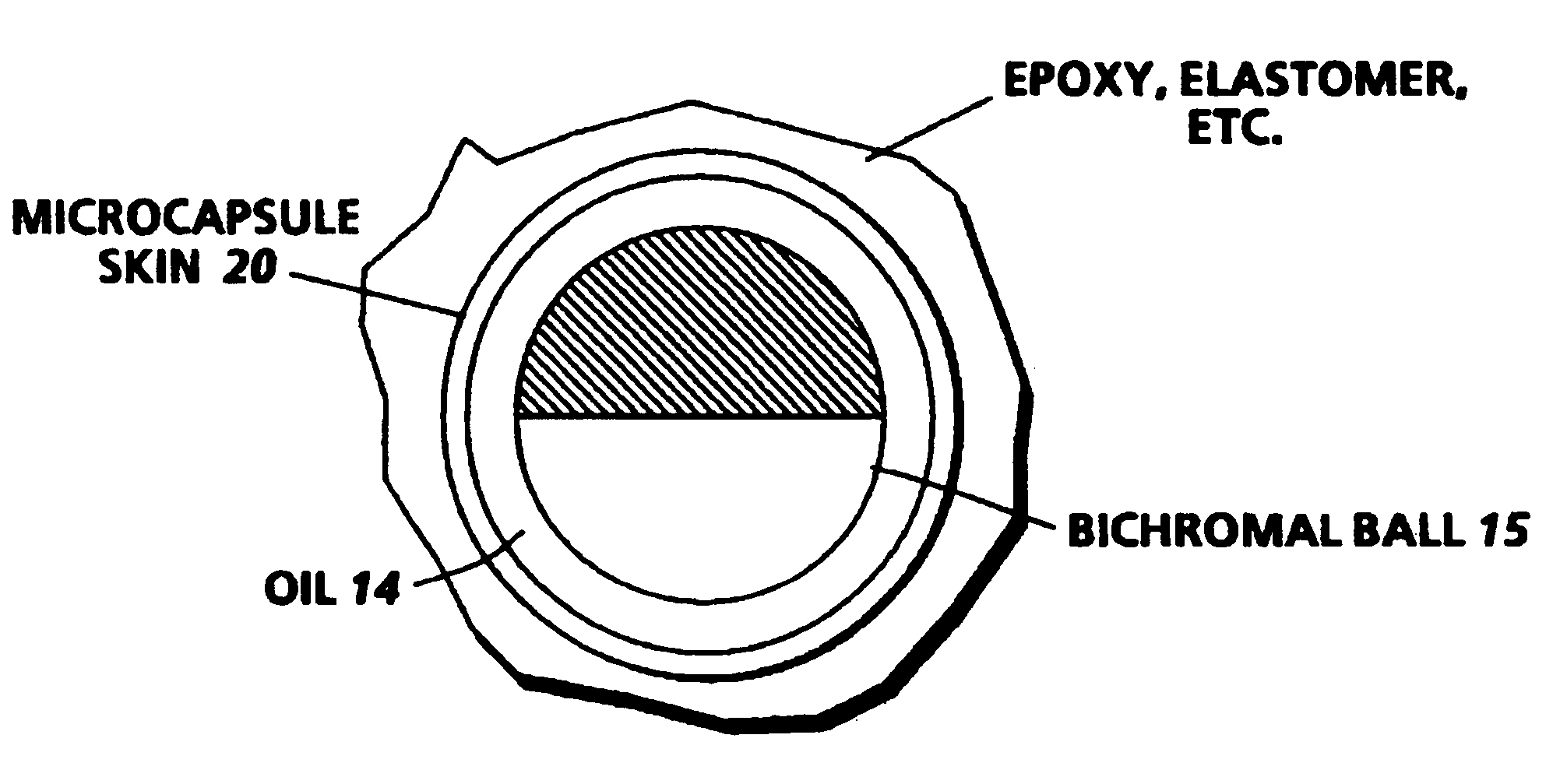
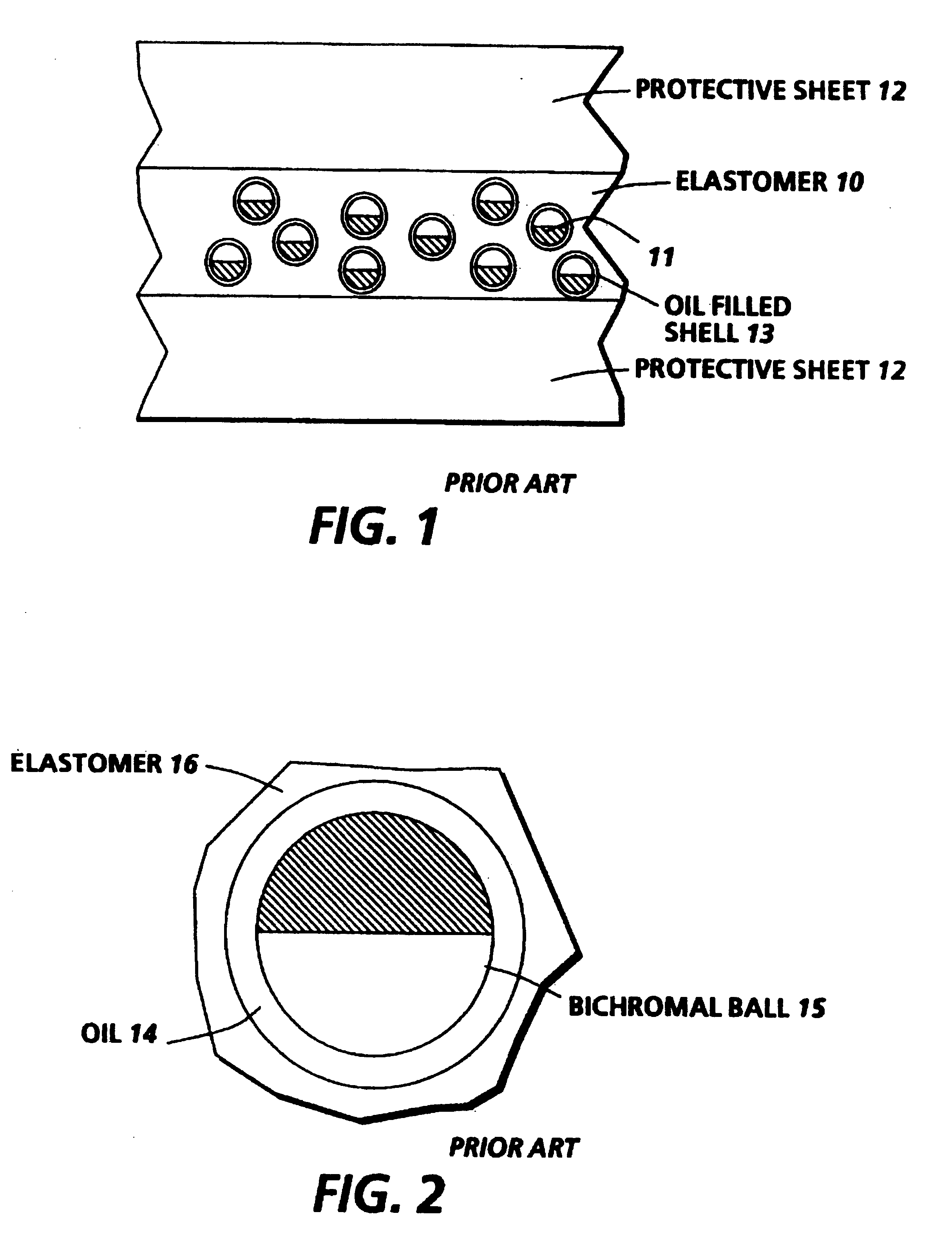
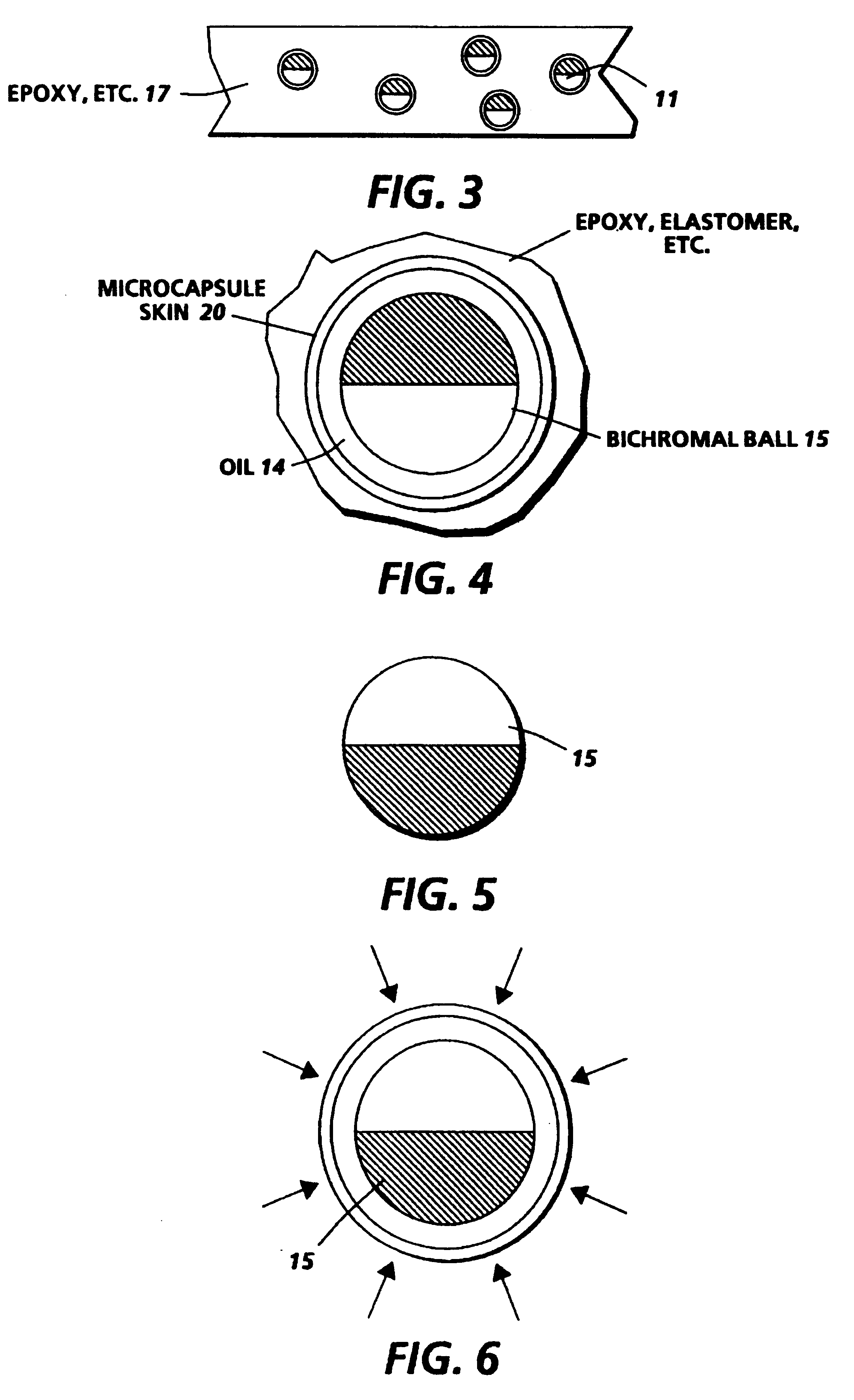
FIG. 1 is a cross section of the prior art version of this twisting ball display. A large number of bichromal balls 11 are mixed into an uncured elastomer which is subsequently spread into a thin layer 10 and cured to form a solid sheet of elastomer. Next this elastomer is soaked in a plasticizing oil which swells the elastomer but generally does not effect the bichromal balls. The result is that a spherical cavity 13 opens up around each bichromal ball, and this cavity subsequently fills with the plasticizing liquid. Finally the plasticized elastomer is bonded between two protective, transparent sheets of plastic or glass, 12, one or both of which might have a transparent .[.condicting.]. .Iadd.conducting .Iaddend.coating. FIG. 2 is an enlarged view of the bichromal ball 15 surrounded by plasticizing oil 14 within a cavity in elastomer 16.

The substrate material used in the prior art twisting ball display was largely limited to the class of elastomer materials, because these materia...


PUM

PropertyMeasurementUnit
coloraaaaaaaaaa
electrical characteristicsaaaaaaaaaa
adhesiveaaaaaaaaaa

Abstract

Bichromal balls have two hemispheres, typically one black and one white, each having different electrical properties. Each ball is enclosed within a spherical shell and then a space between the ball and shell is filled with a liquid to form a microsphere so that the ball is free to rotate in response to an electrical field. The microspheres can then be mixed into a substrate which can be formed into sheets or can be applied to any kind of surface. The result is a film which can form an image from an applied electrical field.

Description

BACKGROUND OF THE INVENTIONA "twisting ball" medium for displaying an image comprising internal bichromal balls that rotate to show either black or white hemispheres in response to an externally applied electrical field, and that are contained in individual liquid filled spherical shells that are in turn dispersed in a transparent binder, which is usually solid when used.U.S. Pat. Nos. 4,126,854 and 4,143,103 describe a twisting ball display and are incorporated by reference herein. These patents describe a display system in which the display panel is comprised of spherical balls which have an optical and an electrical anisotropy due to each hemisphere surface having a different color and electrical charge in contact with a liquid. These spherical particles are imbedded in a solid substrate and a slight space between each ball and the substrate is filled with a liquid so that the balls are free to rotate, in a changing electrical field, but can not migrate from one location to anoth...

Claims


Application Information

Patent Timeline
Patent Type & Authority Patents(United States)
IPC IPC(8): G02B26/02G09F9/37
CPCG02B26/026G09F9/372Y10T428/25Y10T428/2984Y10T428/2985Y10T428/249994
Inventor SHERIDON, NICHOLAS K.
Owner XEROX CORP
Why Eureka
Try Eureka