Pulsed ion beam source

a technology of ion beams and ion beams, which is applied in the direction of ion beam tubes, electric discharge lamps, instruments, etc., can solve the problems of inability to commercialize, add complexity, size and expense to the system employing such map ion sources, and no commercial implementation has resulted, etc., to achieve efficient localization of gas puffs, reduce the rotation of ion beams, and reduce the effect of ion beam rotation

Inactive Publication Date: 2001-03-20
SANDIA
View PDF1 Cites 5 Cited by
  • Summary
  • Abstract
  • Description
  • Claims
  • Application Information

AI Technical Summary

Benefits of technology

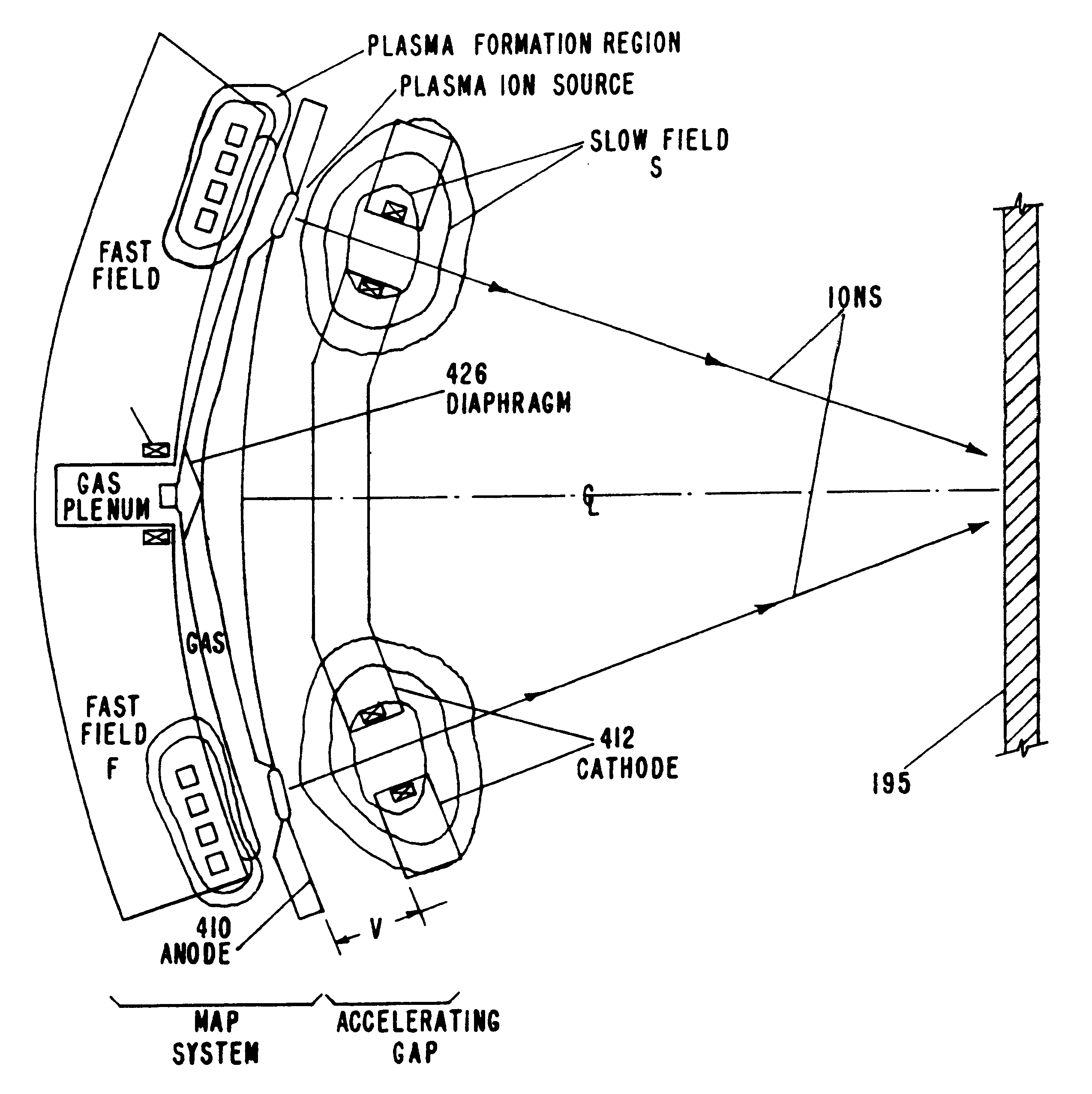
The present invention provides a new type of magnetically-confined anode plasma ion beam source. The new MAP ion diode has improvements in a number of areas. Its magnetic fields are designed to have a profile such that the separatrix (B=0) between the fast coil field and the slow coil field is located near the anode to minimize or eliminate ion beam rotation. The gas nozzle is designed to produce a high mach number (supersonic) gas flow rate to efficiently localize the gas puff introduced into the ionizing region proximate the fast coil. Means are also provided to create an adjustable bias field to control the formation position of the plasma. A fast ringing field is imposed on the gas puff as it is delivered to the ionizing region to pre-ionize the gas. These and other improvements contribute to the MAP ion beam source of this invention.

Problems solved by technology

The downstream electric and / or magnetic fields add complexity, size and expense to a system employing such MAP ion sources.
Although experiments with prior art ion diode sources have indicated that ion beams might be useful for these sort of surface treatments, no commercial implementations have resulted.
The use of ion beams for thermally altering the near surface characteristics of a material has been fraught with substantial problems.
Most notable of the limitations with existing ion beam technologies have been: 1) high costs per area treated; 2) the inability to generate a large number of pulses without the costly replacement of ion beam generator components; 3) low repetition rates; 4) low average power; and 5) the inability to reliably produce a uniform ion beam of a single selectable ion species.
Other difficulties arising from flashover include: production of large quantities of neutral gas that makes high repetition rate difficult, generation of debris which can contaminate surfaces being treated, and non-uniformity and irreproducibility of the beam in some cases due to the localized and difficult to control nature of flashover, as well as the detrimental beam rotation discussed above.
First, existing pulsed power supplies are not able to generate electrical pulses at high repetition rates having the voltage, pulse width (i.e., nominal temporal duration), and power required to generate the ion beams needed (i.e., consistent with the discussion above) for the various beneficial applications described herein.
This limitation renders commercial exploitation impractical.
Second, the design of existing ion beam generators does not allow repetitive operation for an extended number of operating cycles (>>10.sup.3) without replacement of major components.
This limitation would require a maintenance time--manufacturing time ratio incompatible with routine manufacturing operations.
Third, existing ion beam generators generally operate with electrical efficiencies <5%, thus presenting major challenges to the pulsed power supply and the cooling system of the generator.
These limitations and others have made it impossible to routinely utilize the ion beam technology described above for surface treating materials.

Method used


Image

  • Pulsed ion beam source
  • Pulsed ion beam source
  • Pulsed ion beam source

Examples


Embodiment Construction

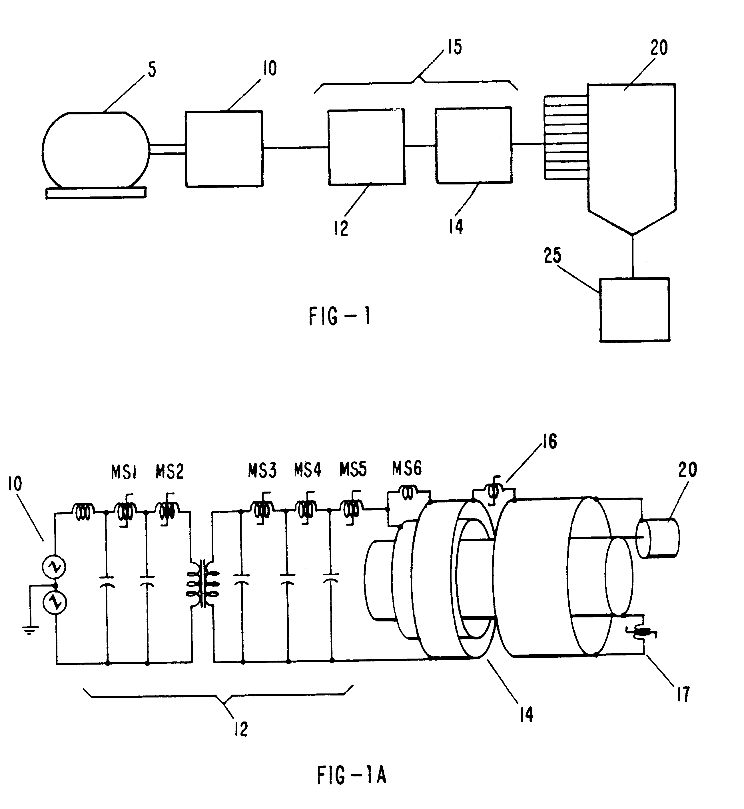
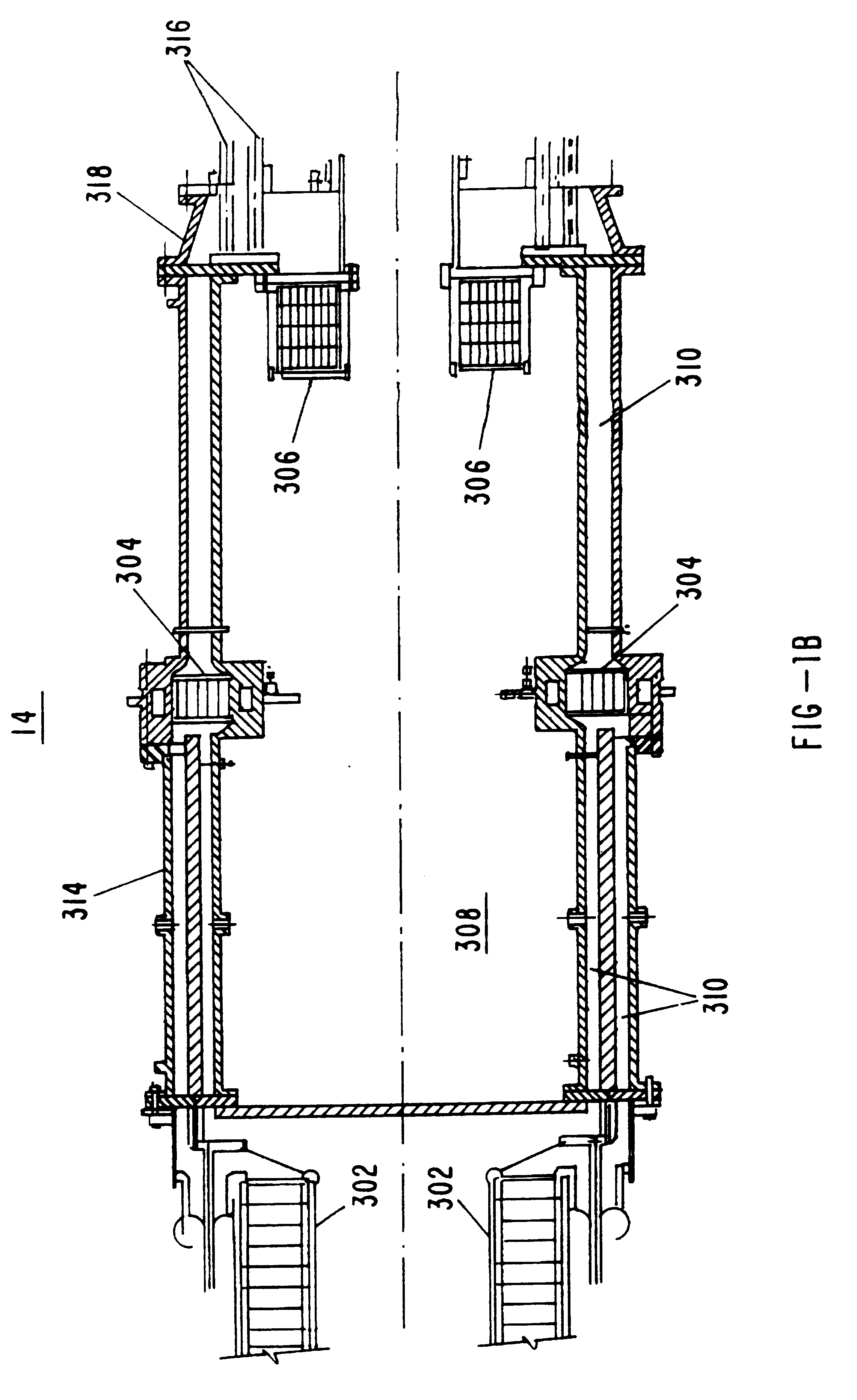
The following discussion is a description of one system which can be utilized to produce the ion beams for surface treatment of various materials. This system has two major subsystems, the pulsed power source and the MAP ion diode.

The MAP ion diode which forms the present invention, when combined with the RHEPP source, provides for an ion beam generator system capable of high average power and repetitive operation over an extended number of operating cycles for treating large surface areas of materials at commercially attractive costs. In particular, the ion beam generator of the present invention can produce high average power (1 kW-4 MW) pulsed ion beams at 0.1-2.5 MeV energies and pulse durations or lengths of from about 10 nanoseconds (ns)-2 microseconds (.mu.s) or longer as necessary for the particular application. The ion beam generator can directly deposit energy in the top 50 micrometers (.mu.m) of the surface of a material. The depth of treatment can be controlled by varyin...


PUM

PropertyMeasurementUnit
rise timeaaaaaaaaaa
rise timeaaaaaaaaaa
voltageaaaaaaaaaa

Abstract

An improved magnetically-confined anode plasma pulsed ion beam source. Beam rotation effects and power efficiency are improved by a magnetic design which places the separatrix between the fast field flux structure and the slow field structure near the anode of the ion beam source, by a gas port design which localizes the gas delivery into the gap between the fast coil and the anode, by a pre-ionizer ringing circuit connected to the fast coil, and by a bias field means which optimally adjusts the plasma formation position in the ion beam source.

Description

FIELD OF THE INVENTIONThis invention relates generally to apparatus for producing ion beams. More particularly it relates to magnetically-confined anode plasma (MAP) ion sources. Still more particularly, it relates to such MAP ion sources as are designed to produce minimum ion beam rotation and precise control over the ion species present in the beam.BACKGROUNDA variety of ion beam sources exist. MAP ion sources are particularly interesting because of their ability to shield the ion source structure from the destructive effects of the ion plasma by the magnetic shielding created by the magnetic structure of the MAP ion source.However, most of the prior art MAP ion sources were designed to be used in a beam line that also included downstream steering and confinement of the produced ion beams by various electric and / or magnetic fields. This steering and confinement was necessary because of the beam rotation created by the magnetic structure of these MAP ion sources which imparted sign...

Claims


Application Information

Patent Timeline
Patent Type & Authority Patents(United States)
IPC IPC(8): B29C59/16B29C59/00H01J27/14H01J27/02B29C35/08
CPCB29C59/16B29C2035/0872H01J27/14H01J2237/08H01J2237/31701
Inventor GREENLY, JOHN B.
Owner SANDIA
Why Eureka
Try Eureka