Wheel-activated vehicle restraint system

Inactive Publication Date: 2002-03-05
RITE HITE HLDG CORP
View PDF80 Cites 30 Cited by
  • Summary
  • Abstract
  • Description
  • Claims
  • Application Information

AI Technical Summary

Benefits of technology

In accordance with that aim, it is a primary object of the invention to provide a restraint device which is capable of accommodating vehicles of widely varying configurations and tire sizes.
A further object of the invention is to provide a restraint device which is compact and has a low profile for accommodating vehicles having low undercarriages or low tailgates.
It is a related object to provide a restraint with a low profile relative to the roadway such that, during actuation, the restraint does not interfere with any other portion of the vehicle beside the tire, i.e. ICC bars, tailgates, fenders, or mud flaps, thus ins

Problems solved by technology

Without such securement, there is a potential hazard that the vehicle could be inadvertently moved away from the loading dock during the loading/unloading operation.
If this were to occur without the knowledge of the dock personnel, they could continue to attempt to move cargo into or out of the vehicle assuming the presence of the vehicle at the dock, and injury to personnel or damage to dock equipment could occur.
Previous attempts to employ roadway positioned restraints to prevent the vehicle from prematurely moving away from the loading dock have been largely unsuccessful, or have several shortcomings.
Attempts to place wheel blocks underneath and wedged in front of the vehicles' wheels have been unsuccessful because 1) the blocks are easily lost or damaged; 2) the blocks may not operate effectively due to a slippery road surface from oil, rain, ice, or snow; 3) the bloc

Method used


Image

  • Wheel-activated vehicle restraint system
  • Wheel-activated vehicle restraint system
  • Wheel-activated vehicle restraint system

Examples


Embodiment Construction

While the invention will be described in connection with certain preferred embodiments, there is no intent to limit it to those embodiments. On the contrary, the intent is to cover all alternatives, modifications, and equivalents included within the spirit and scope of the invention as defined by the appended claims.

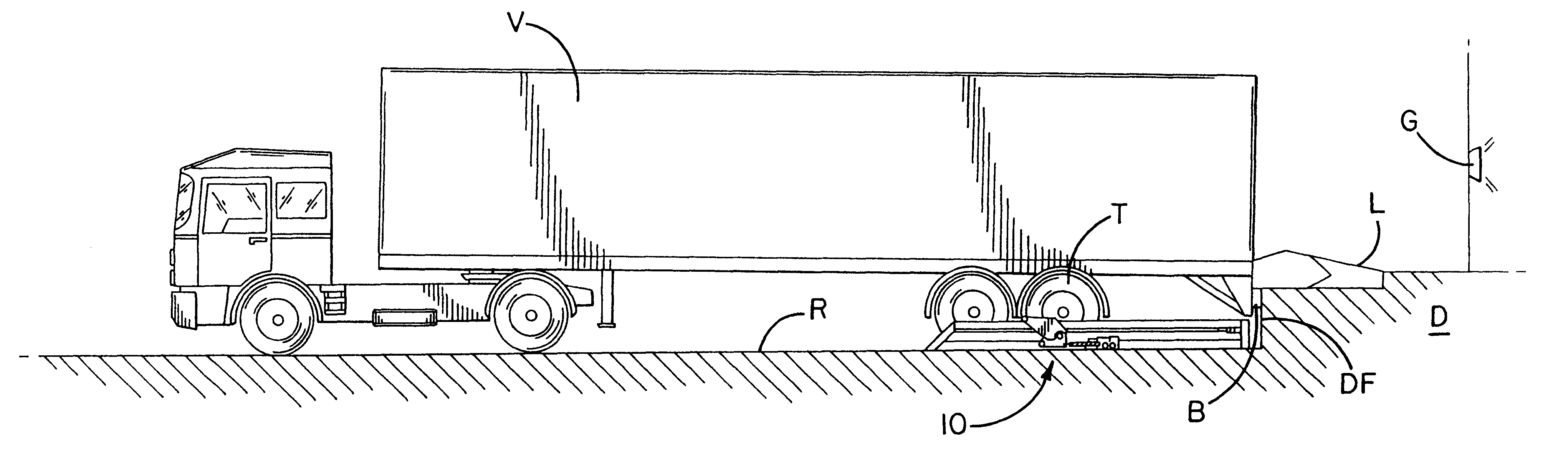
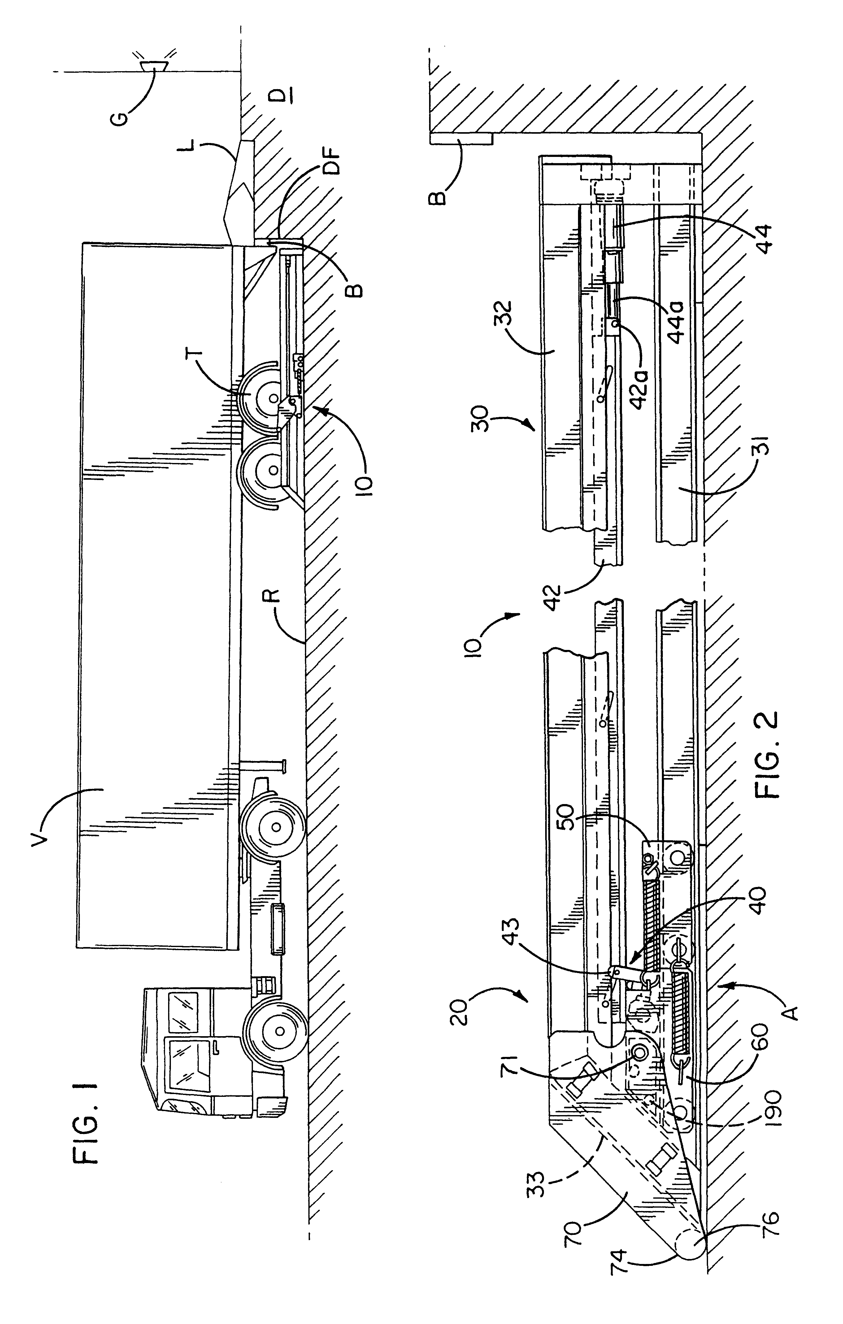
The tire-actuated vehicle restraint device according to the present invention is shown in an illustrative operating environment in FIG. 1. The restraint device 10 engages a leading tire T of a vehicle V to maintain the vehicle V in a loading / unloading position adjacent a loading dock D. The term "tire" as used herein refers to the combination of a wheel and a tire rotatably mounted to a vehicle V. Thus, an action performed on a tire is also performed on a wheel. Tire T is referred to as the "leading" tire as it is the first to approach the dock D as the vehicle V backs into position over the roadway R. As is conventional, the dock D shown in FIG. 1 includes a dock levele...


PUM


Abstract

A wheel-activated vehicle restraint system including a support structure disposed beside the path of the vehicle approaching the dock, and including a guide member extending away from the dock face, and an elevated supporting member. A trigger assembly is operatively connected to the guide member, and initially engages the wheel of the vehicle as it rolls toward the dock. A locking arm operatively engages the supporting member to move from a stored position to a chocking position on the wheel as the wheel engages the trigger and moves it toward the dock. A trolley assembly operatively connects the trigger assembly and the locking arm, the trolley assembly and the locking arm being connected at a connection point. The trigger assembly is selectively positionable relative to the connection point in response to the dimensions of the wheel, and the locking arm engages a bottom portion of the wheel, and moves along the peripheral surface of the wheel to a chocking position as the wheel continues to push the trigger assembly toward the dock.

Description

FIELD OF THE INVENTIONThe invention relates generally to a system for restraining a vehicle adjacent a loading dock, and more specifically to a wheel-actuated vehicle chocking device.BACKGROUND OF THE INVENTIONIn the loading and unloading of vehicles at a loading dock, heavy equipment such as forklifts pass into and out of the vehicle to facilitate and expedite the unloading and / or loading of the vehicle. Accordingly, it is imperative that the vehicle remain in a fixed abutting relationship relative to the loading dock to prevent accidents, and to protect the safety of dock personnel. Without such securement, there is a potential hazard that the vehicle could be inadvertently moved away from the loading dock during the loading / unloading operation. If this were to occur without the knowledge of the dock personnel, they could continue to attempt to move cargo into or out of the vehicle assuming the presence of the vehicle at the dock, and injury to personnel or damage to dock equipmen...

Claims


Application Information

Patent Timeline
IPC IPC(8): B65G69/00
CPCB65G69/005
Inventor SPRINGER, SCOTT L.HAHN, NORBERTVAN DE WIEL, HANSBOON, MARCELDE BEER, FRANK
Owner RITE HITE HLDG CORP
Why Eureka
Try Eureka