Self-diagnosis arrangement for a video display and method of implementing the same

Inactive Publication Date: 2004-06-22
SAMSUNG ELECTRONICS CO LTD
View PDF7 Cites 16 Cited by
  • Summary
  • Abstract
  • Description
  • Claims
  • Application Information

AI Technical Summary

Benefits of technology

It is still another object of the present invention to provide a self-diagnosis arrangement for a video display and method thereof wherein a pictorial image in .Iadd.a .Iadden

Problems solved by technology

In the arrangement of such a conventional type display apparatus however, a raster signal for displaying a raster pattern is limited to only utilizing either a flyback pulse or a RC oscillation circuit, for example, such as one of a bridge type or of a shifted-phase type, thereby displaying a single image pattern on a screen.
A synchronizing signal employed

Method used


Image

  • Self-diagnosis arrangement for a video display and method of implementing the same
  • Self-diagnosis arrangement for a video display and method of implementing the same
  • Self-diagnosis arrangement for a video display and method of implementing the same

Examples


Embodiment Construction

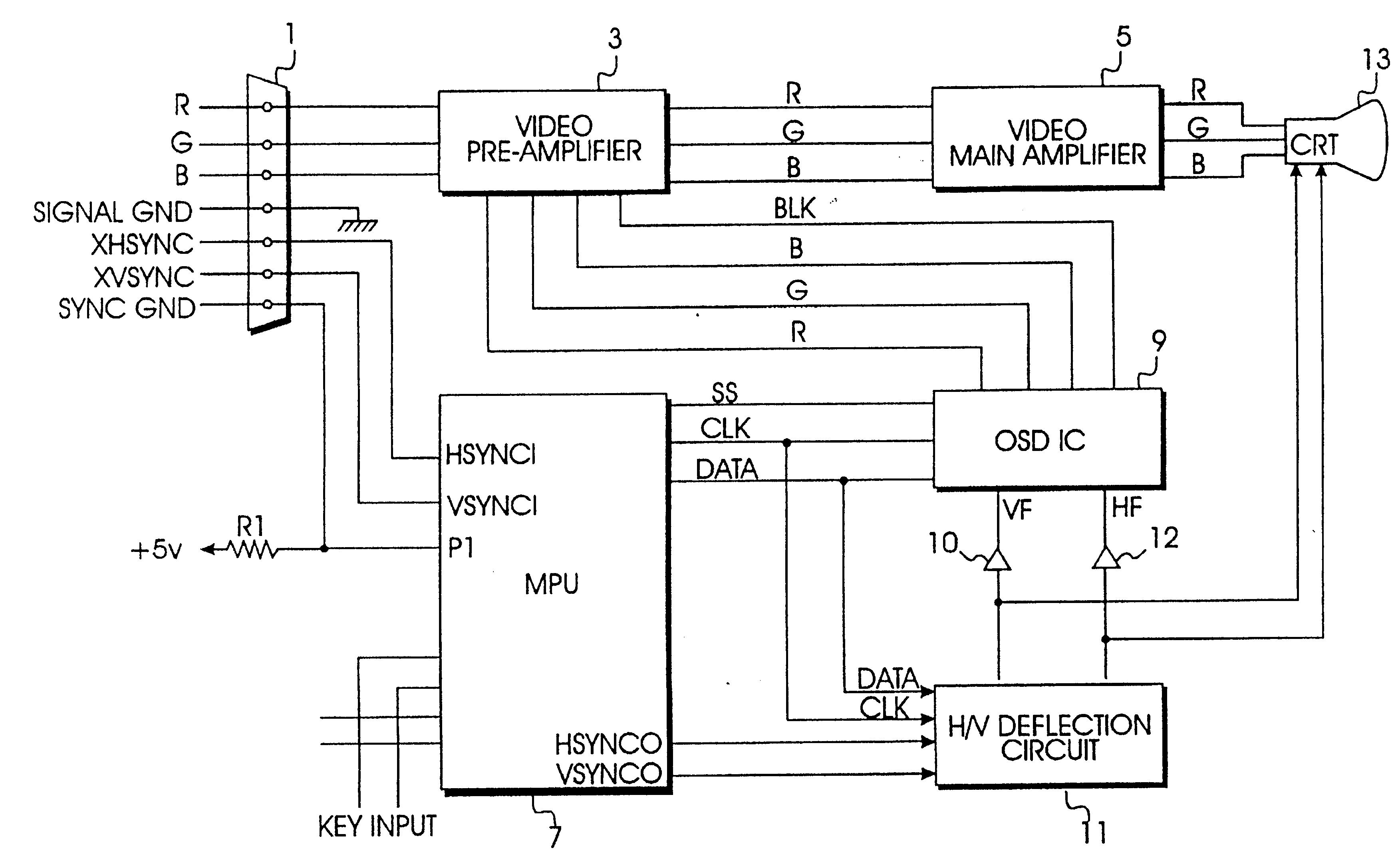
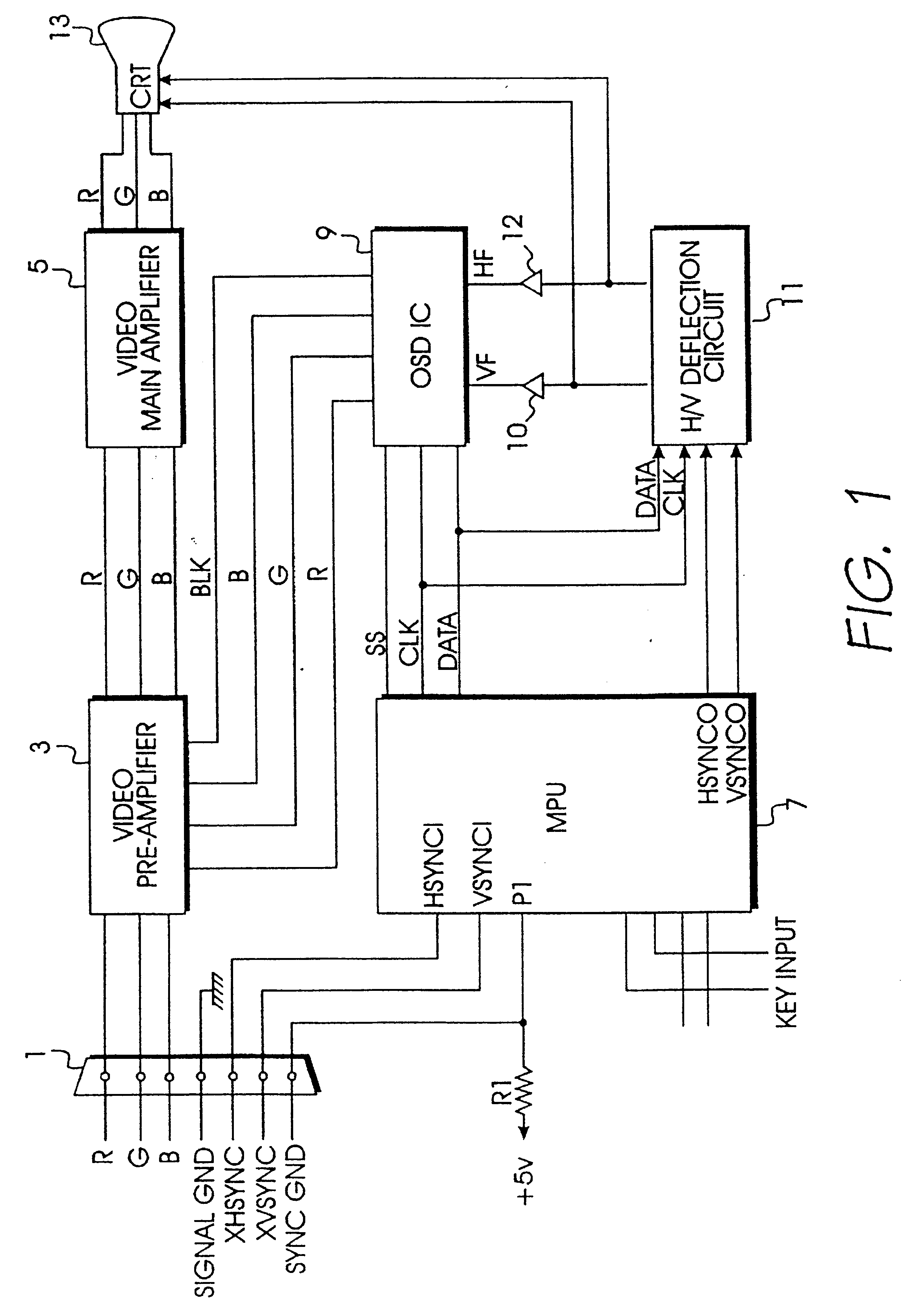
Turning now to the drawings and referring to FIG. 1, a schematic block diagram of a preferred embodiment of the present invention is shown. In a normal state of connection between cable connector 1, and an external system, video signals including video component signals R (red), G (green),and B (blue) (hereinafter, referred to as a "RGB video signal") and external horizontal and vertical synchronizing signals XHSYNC and XVSYNC (hereinafter, referred to as an "external H / V sync signal) are input through a cable into a video display via cable connector 1.

A video pre-amplifier 3, receives the RGB video signal from cable connector 1, amplifies the received RGB video signal and then mixes the amplified RGB video signal with a video signal supplied from an on-screen display integrated circuit (hereinafter, referred to as an "OSD video signal") for output to a video main amplifier 5. Video main amplifier 5 amplifies the magnitude of the mixed video signal output from video pre-amplifier 3,...


PUM


Abstract

A self-diagnostic arrangement for a video display apparatus and method effectuating the same is disclosed. The apparatus according to the present invention includes a cable connector, amplifiers and a cathode ray tube and comprises a microprocessor storing information on a display status, for selectively switching signals to generate horizontal and vertical sync signals for displaying a variety of self-diagnostic displays, an on screen display IC for supplying a blanking signal and a video signal correspondingly responsive to information supplied from the microprocessor and a H/V deflection circuit for supplying on screen display video. signals to the CRT. There is also provided a method of self-diagnosis, which comprises the steps of generating internal horizontal and vertical .[.sync.signals.]. .Iadd.sync signals .Iaddend.of predetermined frequency levels and displaying self-diagnostic screens representing video component colors and a display status.

Description

CROSS REFERENCE TO RELATED APPLICATIONSThis application make reference to, incorporates the same herein, and claims all benefits acruing under 35 U.S.C .sctn.119 from an application entitled A DISPLAY APPARATUS HAVING SELF-DIAGNOSTIC FUNCTION earlier filed in the Korean Industrial Property Office on 22 Oct. 1994 and assigned Ser. No. 27039 / 1994.BACKGROUND OF THE INVENTIONThe present invention relates to an apparatus for a video display, and .[.a.]. more particularly, to a video display apparatus having a self-diagnostic circuit and method of implementing self-diagnosis by utilizing the same.Conventionally, in a video display apparatus such as a monitor for a personal computer system, there is provided a raster arrangement for preventing a user from mistakenly believing a monitor is not operating properly when no raster pattern is displayed on the monitor's screen when no video signal is input during a power-on state. An exemplary apparatus including such arrangement is disclosed in ...

Claims


Application Information

Patent Timeline
IPC IPC(8): G09G1/08G09G1/06H04N5/44G01R31/28G09G1/16H04N17/04
CPCG01R31/2825G09G1/165G09G2320/08G09G2330/08H04N17/045
Inventor KIM, YOUNG-HEE
Owner SAMSUNG ELECTRONICS CO LTD
Why Eureka
Try Eureka