Movable target system in which power is inductively transformed to a target carrier

a target carrier and inductive transformation technology, applied in the direction of movable targets, target ranges, weapons, etc., can solve the problems of brush wear with use, lower voltage supplied to electric motors, and interference with the electrical connection between brushes and conductor strips

Inactive Publication Date: 2004-06-29
ACTION TARGET ACQUISITION
View PDF32 Cites 38 Cited by
  • Summary
  • Abstract
  • Description
  • Claims
  • Application Information

AI Technical Summary

Benefits of technology

The present invention is embodied in an improved movable target system which meets the need heretofore expressed. Power is inductively transferred to a target carrier movable between first and second locations. The transferred power is used to power electrical equipment on board the target carrier. The electrical equipment may include electric motors, lights, solenoids, and control circuitry for the motors and solenoids. Preferred embodiments of the invention are implemented as track-based systems, as the track provides not only stability to the target carrier, but also protection from stray bullets to the conductive cable.

Problems solved by technology

Such a design suffers from the drawback that bullet fragments and other debris may alight on the conductor strips and thereby interfere with the electrical connection between the brushes and the conductor strip.
Arcing between the brushes and the conductor strips will result in the formation of oxides which will increase the resistance at the connection and result in lower voltages being supplied to the electric motors.
In addition, the brushes tend to wear with use, requiring periodic monitoring and replacement to prevent harmful arcing conditions.
Such a design is rather complex and requires constant frequent lubrication of the threaded shaft and brush type contacts to transfer current to each cable at the take-up spool.
Abrasion to the insulated sheath covering the cable caused by frequent movement of the cable, as well as fatigue and eventual breakage of the cable conductors caused by frequent flexing of the cable are significant problems of this design.
Another problem relates to the need to provide a mechanism which will maintain the power cable (which is no lightweight ribbon cable) neatly folded as the carrier moves toward the cable power source, regardless of the carrier's position on the track.

Method used


Image

  • Movable target system in which power is inductively transformed to a target carrier
  • Movable target system in which power is inductively transformed to a target carrier
  • Movable target system in which power is inductively transformed to a target carrier

Examples


first embodiment

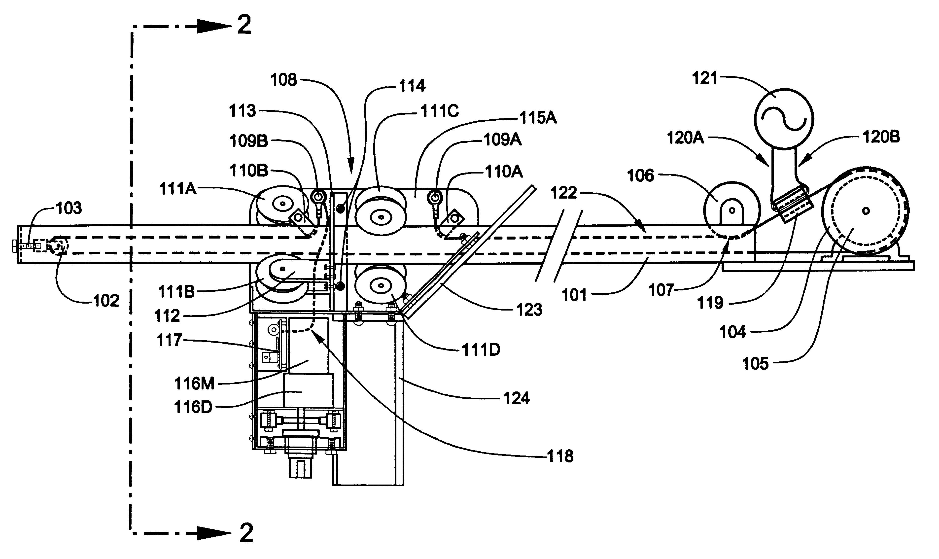
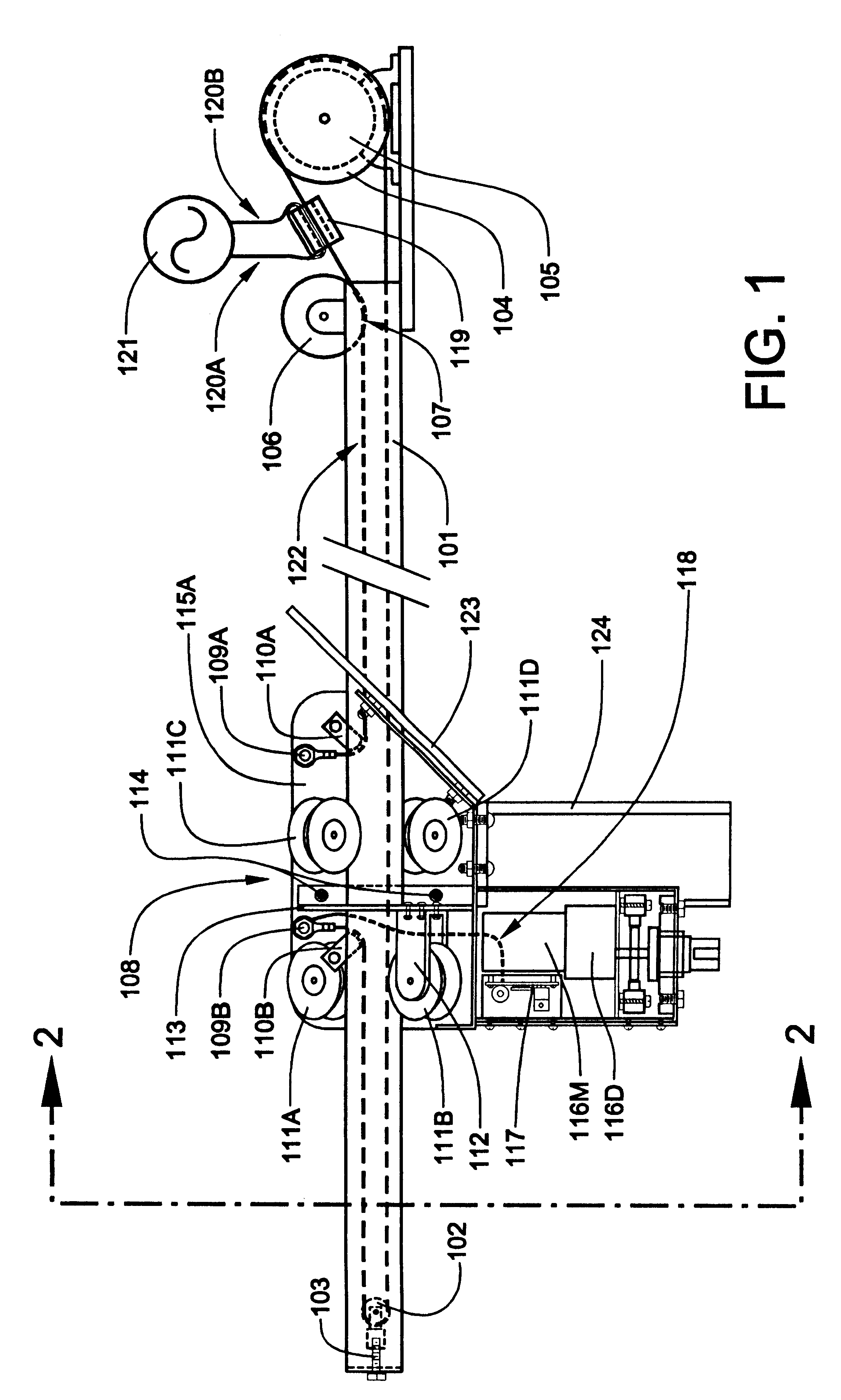
the invention may be characterized as a movable target system having a target carrier that is driven by a movable, looped cable along a track. Electrical power is transferred to the movable cable via a stationary inductor which is inductively coupled to the cable. Power induced in the cable is received by the carrier and used to power electrical equipment on board the carrier. This first embodiment of the invention will now be described.

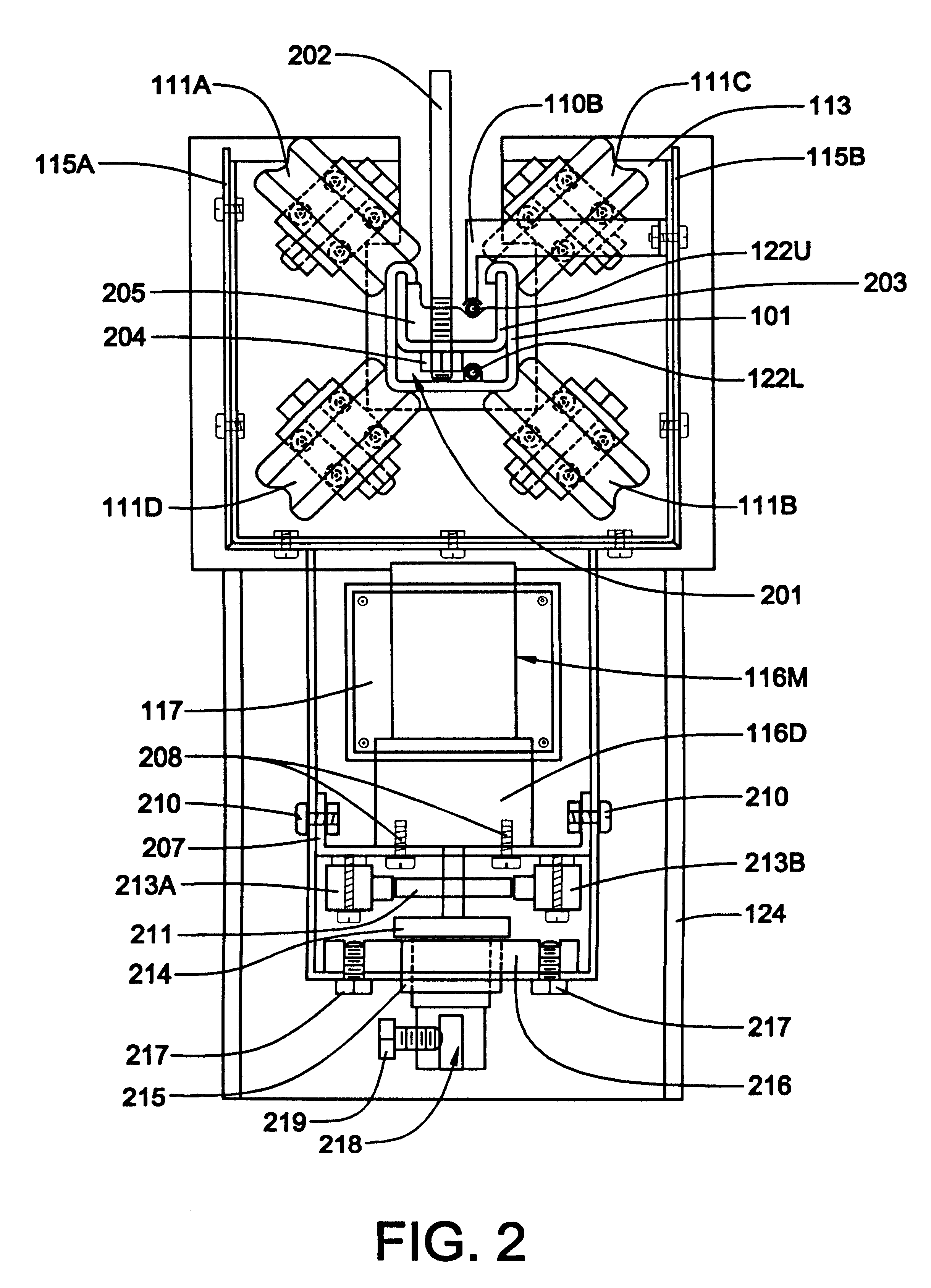
Referring now to FIG. 1, an overhead track 101 of substantially rectangular, U-shaped cross section, having an upward-facing groove or channel (see FIG. 2, item 201) that extends along the length of the track, is provided between two locations between which a target must be movably positionable. A first idler pulley 102 incorporating a tensioning device 103, is mounted within the channel 201 at a first end of the track 101. A drive pulley 104, powered by a drive motor 105, is mounted in line with the channel 201 near the opposite, or second, end of t...

second embodiment

the invention may be characterized as a movable target system having a target carrier movable along a track which encloses a stationary cable to which alternating current is applied. The carrier incorporates onboard electrical equipment that at least includes an electric transport motor. The onboard electrical equipment receives it power from an inductor which slides along the stationary cable. This second embodiment of the invention will now be described.

Referring now to FIG. 4, a conductive overhead track 401 of substantially rectangular, U-shaped cross section, having an upward-facing groove or channel (see FIG. 5, item 501) that extends along the length of the track, is provided between two locations between which a target must be movably positionable. A first cable anchoring device 403A incorporating a cable tensioner 404 is longitudinally aligned with and positioned at one end of the track 401, being electrically connected thereto. An alternating current source 405, having fir...


PUM


Abstract

An improved track-mounted movable target system is disclosed. Power is inductively transferred to a target carrier movable between first and second locations. The transferred power is used to power electrical equipment on board the target carrier. The electrical equipment may include electric motors, lights, solenoids, and control circuitry for the motors and solenoids. Preferred embodiments of the invention are implemented as track-based systems, as the track provides not only stability to the target carrier, but also protection from stray bullets to the conductive cable. For a first embodiment of the invention, power is transferred to a target carrier via a stationary inductor and a movable cable, which also provides motive force to the target carrier. For a second embodiment of the invention, power is transferred to a target carrier via a stationary cable and an inductor movable with the target carrier. For this second embodiment of the invention, electrical equipment on board the target carrier includes a drive motor for moving the carrier bidirectionally along the track. For both embodiments of the invention, communications with the target carrier may be achieved by modulating the frequency of the applied alternating current and demodulating it at the target carrier to provide control signals for control circuitry on board the target carrier.

Description

FIELD OF THE INVENTIONThis invention relates to equipment for target ranges and, more specifically, to movable track-mounted target carriers having onboard electrical equipment to which power must be supplied from an external source. The invention also relates to induction-based electrical power transmission systems.DESCRIPTION OF RELATED ARTMovable target systems typically employ a target carrier that is movable along a rail or track. There is often a requirement that the target attached to the carrier be movable (e.g., pivotable about its vertical central axis). The provision of linear movement to the carrier and movement to the target with respect to the carrier has resulted in various movable target system designs.One solution to providing linear movement to a carrier and pivotal movement to a target makes use of a pair of parallel conductor strips mounted on the track which are electrically insulated from one another and between which a voltage potential is applied. Alternative...

Claims


Application Information

Patent Timeline
Patent Type & Authority Patents(United States)
IPC IPC(8): F41J9/02F41J9/00
CPCF41J9/02
Inventor BATEMAN, KYLE E.
Owner ACTION TARGET ACQUISITION
Why Eureka
Try Eureka