Programmable load transient compensator for reducing the transient response time to a load capable of operating at multiple power consumption levels

a transient response time and load technology, applied in the field of integrated circuits, can solve the problems of increasing system out of regulation, load not receiving the appropriate voltage, etc., and achieve the effect of reducing the transient response time of the system

Inactive Publication Date: 2005-11-22
STMICROELECTRONICS SRL
View PDF21 Cites 17 Cited by
  • Summary
  • Abstract
  • Description
  • Claims
  • Application Information

AI Technical Summary

Benefits of technology

[0007]According to principles of the present invention, a load transient compensator is provided to reduce the transient response time of a system. The load transient compensator has a power supply input terminal, a control input terminal for coupling to a control circuit, and an outpu

Problems solved by technology

The large change in current demand of the microprocessor, which is the load of the system, may bring the system out of regulation during the transient response.
A problem with the above methods is that during the time that the change in current demand is going through the feedback loop, or by the time the monitoring circuit detects that the current demand of the load has changed, the load is not receiving the appropriate voltage.
The present inventor has observed that another problem with the above method is that during the time it takes to detect the change in the current demand the

Method used


Image

  • Programmable load transient compensator for reducing the transient response time to a load capable of operating at multiple power consumption levels
  • Programmable load transient compensator for reducing the transient response time to a load capable of operating at multiple power consumption levels
  • Programmable load transient compensator for reducing the transient response time to a load capable of operating at multiple power consumption levels

Examples


Embodiment Construction

[0016]In order to reduce the transient response time some circuits have added circuit elements described in detail in pending U.S. patent application entitled: “Device for Limiting Transient Variations of a Supply Voltage” by Luc Wuidart, Alain Bailly, and Jean-Michel Ravon, Ser. No. 08 / 935,580, filing date Oct. 17, 1997 (Attorney Docket Number 96-RO-177 and S1022 / 7902), incorporated herein by this reference. Another solution to the problem of reducing the transient response time includes a circuit that changes the bandwidth of the voltage regulator supplying the load. This is described in detail in pending U.S. patent application entitled: “Programmable Bandwidth Voltage Regulator” by Eric Danstrom, Ser. No. 08 / 574,609, incorporated herein by this reference.

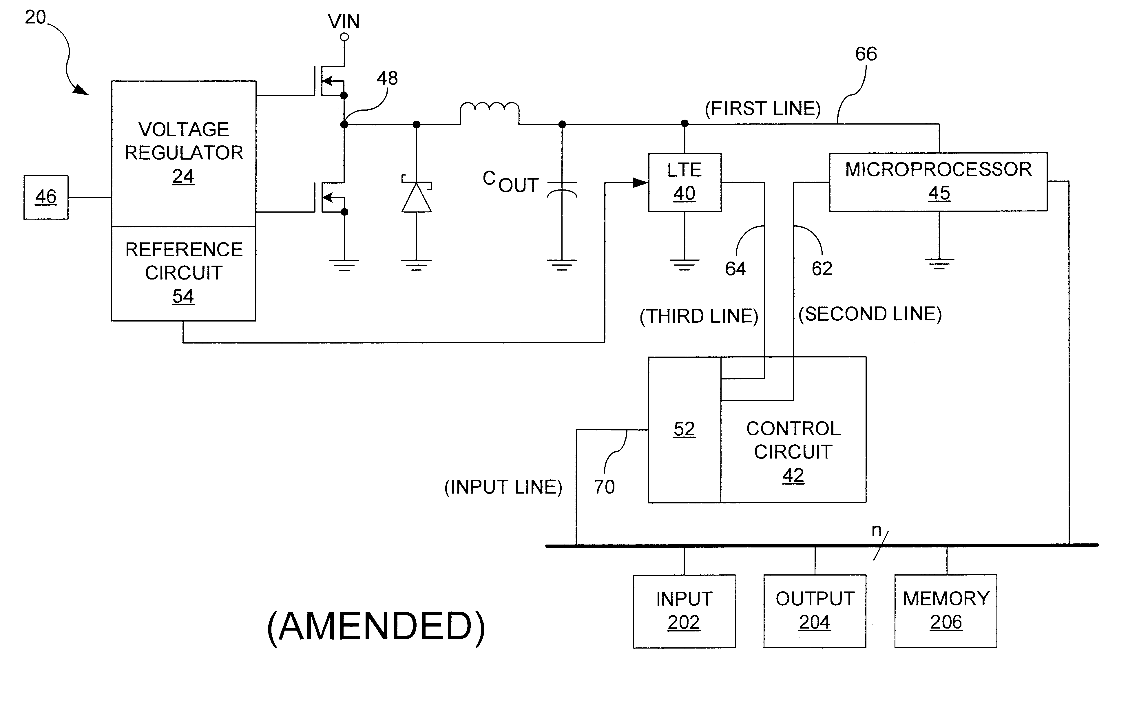
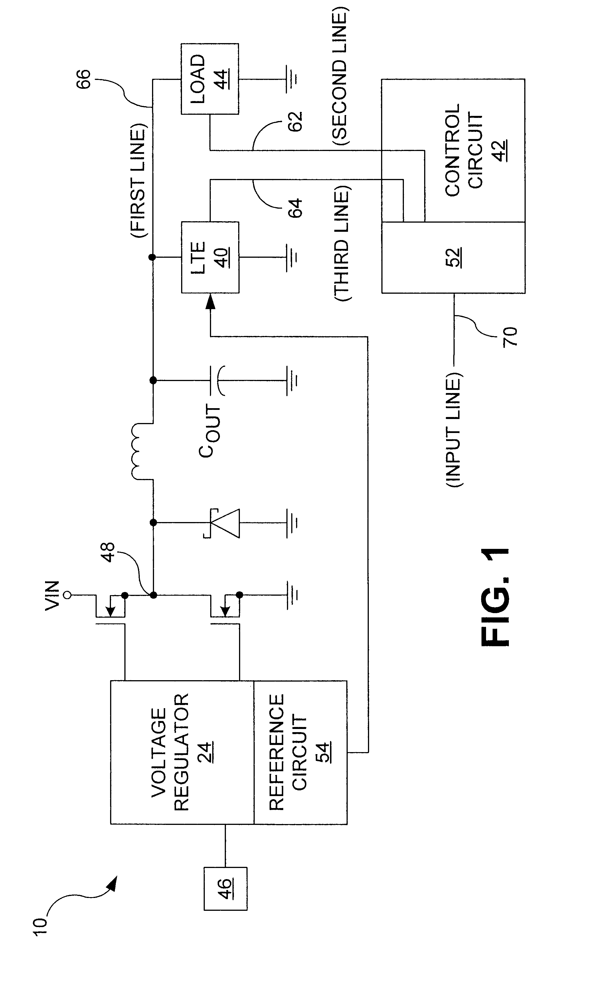
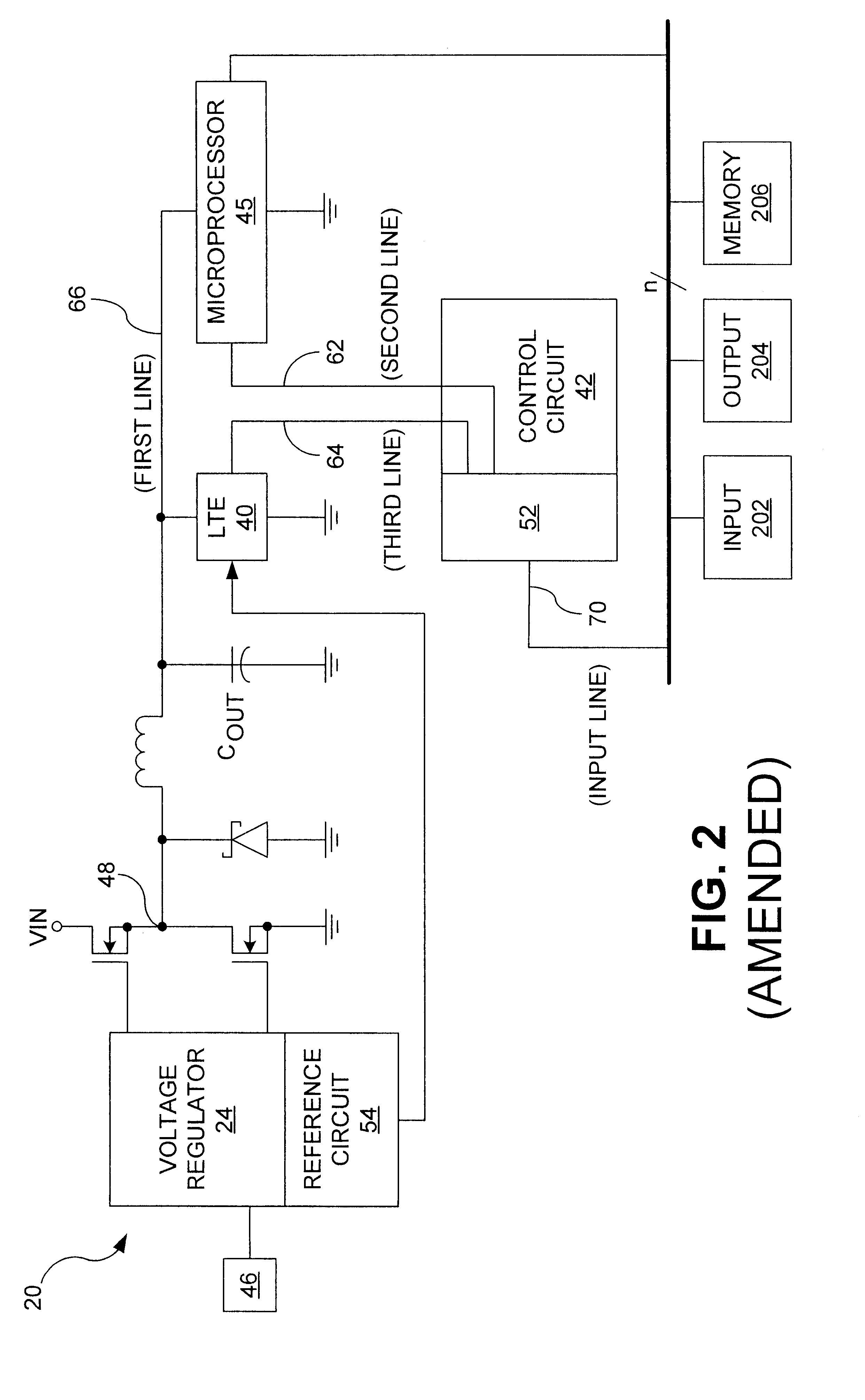
[0017]According to the principles of the present invention, referring to FIG. 1, a load transient compensator is designated generally by the reference numeral 40. The load transient compensator is typically included in an electr...


PUM


Abstract

A load transient compensator and method of operating the load transient compensator for reducing the transient response time to a load capable of operating at either of several consumption levels when the load changes its power consumption level . The load transient compensator has a comparator having an output connected to an input of an upper driver and of a lower driver with the output of each of the driver being connected to a gate of a power transistor. When the load is in sleep mode and is about to start being accessed, the upper driver is turned on to turn on its associated transistor to supply additional current to the load, regulated by the comparison circuit. When the load is in the power up mode and it is about to stop being accessed, the lower driver is turned on to turn on its associated transistor to drain current supplied to the load by a supply, regulated by the comparison circuit. This allows a quicker response to the large changes in current required by the load when the load is changing its level of power consumption without greatly increasing the cost of the system containing the load and without compromising the stability of the system.

Description

TECHNICAL FIELD[0001]The present invention relates to the field of integrated circuits, and is more specifically directed to circuits for reducing the transient response time of a system in delivering required voltage to a load.BACKGROUND[0002]In order to reduce power consumption many electronic components are now capable of operating at several power consumption levels, one of which is typically a power-down or sleep mode. The power-down mode is a low power consumption level that the component can enter into when it is not performing an operation and not being accessed. Reducing the level of power consumption is particularly useful for battery operated devices, such as portable computers, where reducing power consumption increases the battery life, and therefore the time the device can be used without having to either replace or recharge the battery.[0003]A microprocessor consumes a significant amount of power in the full power-up mode, and it is typically accessed only a small por...

Claims


Application Information

Patent Timeline
IPC IPC(8): G05F1/00G05F1/44G06F1/26H02M3/158
CPCG06F1/26H02M3/158H02M1/0045
Inventor DANSTROM, ERIC J.
Owner STMICROELECTRONICS SRL
Why Eureka
Try Eureka