Simulated wave water sculpture

a technology of water sculpture and simulation wave, which is applied in the field of simulation wave water sculpture, can solve the problems of inability to create realistic-looking wave-like shapes or wave-forms, inability to simulate natural propagating wave, and inability to create deep water propagation for many such sculptures, etc., and achieves visual, aural and/or aesthetic appeal.

Inactive Publication Date: 2006-07-11
LIGHT WAVE
View PDF49 Cites 38 Cited by
  • Summary
  • Abstract
  • Description
  • Claims
  • Application Information

AI Technical Summary

Benefits of technology

[0008]In accordance with another embodiment the present invention provides an apparatus for forming a water sculpture, comprising a flow surface with at least a portion thereof having a generally inclined slope. A flow source is provided injecting a shallow flow of water onto the flow surface such that the shallow flow of water flows upwardly onto the inclined slope and substantially conforms to the contours thereof. The flow surface further comprises an upwardly rising section sized and configured so as to induce separation of the shallow flow of water on said upwardly rising section, whereby at least a portion of the water flow assumes an airborne trajectory producing visual, aural and / or aesthetic appeal.

Problems solved by technology

Despite the many approaches to forming water sculptures, there have been relatively few attempts to create realistic-looking wave-like shapes or wave-forms.
Natural propagating wave simulation, however, is not ideal for the formation of water sculptures due to the need for a deep water source.
Because water sculptures typically must operate in a limited amount of space using only limited amounts of water, deep water propagation would be inappropriate for many such sculptures.
Further, the use of deep water creates problems of cost, size and capacity.
Specifically, the reproduction of natural propagating waves in deep water requires expensive water containment and wave generating equipment.

Method used


Image

  • Simulated wave water sculpture
  • Simulated wave water sculpture
  • Simulated wave water sculpture

Examples


example 1

Basic Sheet Flow

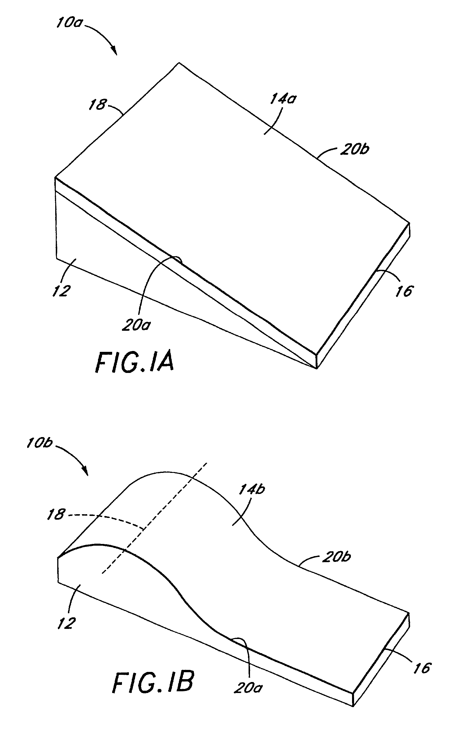
[0053]FIG. 1A shows one embodiment of a simple water sculpture 10a having features of the present invention. Sectional lines as revealed in FIG. 1A are solely for the purpose of indicating the three-dimensional shape in general, and are not illustrative of a specific frame, plan, or profile sections. Rather, it should be noted that a wide variety of dimensions and configurations for the water sculpture 10a are compatible with the principles and teachings of the present invention. Therefore, these principles and teachings should not be construed to be limited to any particular configuration illustrated in the drawings or described herein.

[0054]The water sculpture 10a generally comprises a subsurface structural support 12 and a flow surface 14a, defined by upstream edge 16, downstream edge 18, and side edges 20a and 20b. The flow surface 14a is preferably smooth and can be a skin placed over the sub-surface structural support 12, or the structures can be integrated tog...

example 2

Simulated White Water Bore

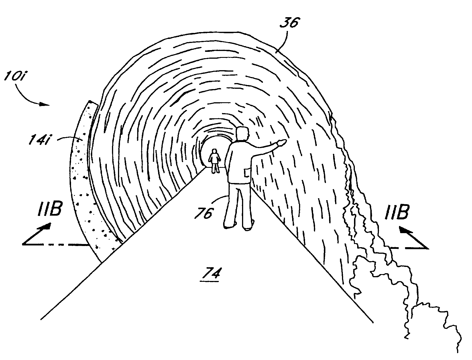
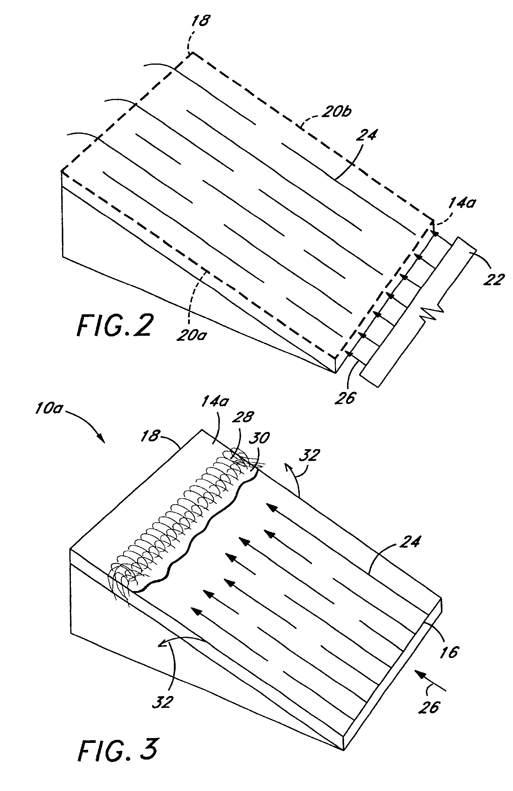
[0058]FIG. 3 illustrates a water sculpture 10 with a flow profile that simulates a stationary white water bore. When the velocity (i.e., kinetic energy) of an upwardly inclined supercritical sheet flow 24, moving in direction 26, is less than the gravitational potential energy downstream of the upper edge or ridge line 18, then sheet flow 24 will form a hydraulic jump 28 prior to reaching downstream ridge line 18. Accordingly, white water 30 will roll downward and to the side as run-off water 32, and, an effect similar to a stationary white water bore will form on the flow surface 14a. Maintenance of this hydraulic state requires that the kinetic energy of supercritical flow 24 always be less than the potential energy at the downstream edge or ridge line 18. The relative position of the hydraulic jump 28 will be determined by the velocity of the supercritical flow 24. The higher the velocity, the higher the position of the hydraulic jump 28 upon flow surfac...

example 3

Simulated Spilling Wave

[0059]A simulated spilling wave with a smooth unbroken shoulder may be created on a flow surface by two general methods: (1) a cross-stream velocity gradient and (2) a cross-stream pressure gradient. The use of either method depends upon overall objectives and constraints of the flow surface structure and available flow characteristics. A cross-stream velocity gradient is the preferred method when the structure of the flow surface is limited to a symmetrical configuration such as flow surface 14a shown in FIG. 4A. A cross-stream pressure gradient is the preferred method when the initial supercritical flow 24 moving up the flow surface has constant velocity such as shown in FIG. 4B.

[0060]FIG. 4A depicts one preferred method for producing a simulated spilling wave with a smooth unbroken shoulder. This wave is created by introducing a cross-stream velocity gradient to a supercritical flow of water that moves in direction 26 up the flow surface 14a with a level ri...


PUM


Abstract

A water sculpture is provided having a an upwardly inclined flow surface. A flowing body of water is caused to flow upon the flow surface simulating various desired wave shapes. A variety of aesthetic wave shapes can be created, such as an unbroken wave face, a white water bore, a spilling breaking wave, or a tunnel wave. In one embodiment a walk-through water sculpture is provided such as for an entranceway of a building or the like.

Description

BACKGROUND OF THE INVENTION[0001]1. Field of the Invention The present invention relates in general to the formation of water sculptures, and, more particularly, to a method and apparatus for providing a flowing body of water on an inclined surface to produce simulated wave shapes for aesthetic purposes such as for water fountains, water sculptures and the like.[0002]2. Description of the Related Art[0003]The concept of using water to create shapes of aesthetic beauty can broadly be categorized in the field of water sculpture. Examples of water sculpture can be seen in water fountains, water geysers and man-made or simulated rivers and waterfalls. These types of sculptures demonstrate numerous possibilities for creating different aesthetic water shapes. For instance, in the case of a man-made river, water can be shaped by being directed over and around various obstacles such as rocks. Water can also be made to fall from heights, as in waterfalls and fountains. Certain fountains may ...

Claims


Application Information

Patent Timeline
Patent Type & Authority Patents(United States)
IPC IPC(8): A63B69/00B05B17/08
CPCA63C19/00B05B17/085
Inventor LOCHTEFELD, THOMAS J.
Owner LIGHT WAVE
Why Eureka
Try Eureka