Eureka AIR delivers breakthrough ideas for toughest innovation challenges, trusted by R&D personnel around the world.

Durable turbine nozzle

Inactive Publication Date: 2007-01-23
GENERAL ELECTRIC CO
View PDF35 Cites 27 Cited by
  • Summary
  • Abstract
  • Description
  • Claims
  • Application Information

AI Technical Summary

Benefits of technology

[0010]A turbine nozzle includes a plurality of vanes joined at opposite ends to outer and inner bands. The inner band has a forward hook which is segmented to reduce thermal mismatch. And, in additional embodiments the vane includes an impingement baffle having preferential cooling.

Problems solved by technology

Such extended life is difficult to achieve since the nozzles are subject to various differential temperatures during operation which create thermal loads and stress therefrom.
And, temperature distributions and heat transfer coefficients of the combustion gases channeled through the nozzle vary significantly and increase the complexity of providing corresponding cooling.
However, these nozzles are beginning to experience distress at high cycle operation which may require their replacement prior to their expected useful life.
Nozzle distress is caused by locally high heat transfer coefficients in different regions of the nozzle at which corresponding cooling is limited.
Thermal gradients lead to thermal stress, which adversely affect the useful life of the nozzle.

Method used


Image

  • Durable turbine nozzle
  • Durable turbine nozzle
  • Durable turbine nozzle

Examples


Embodiment Construction

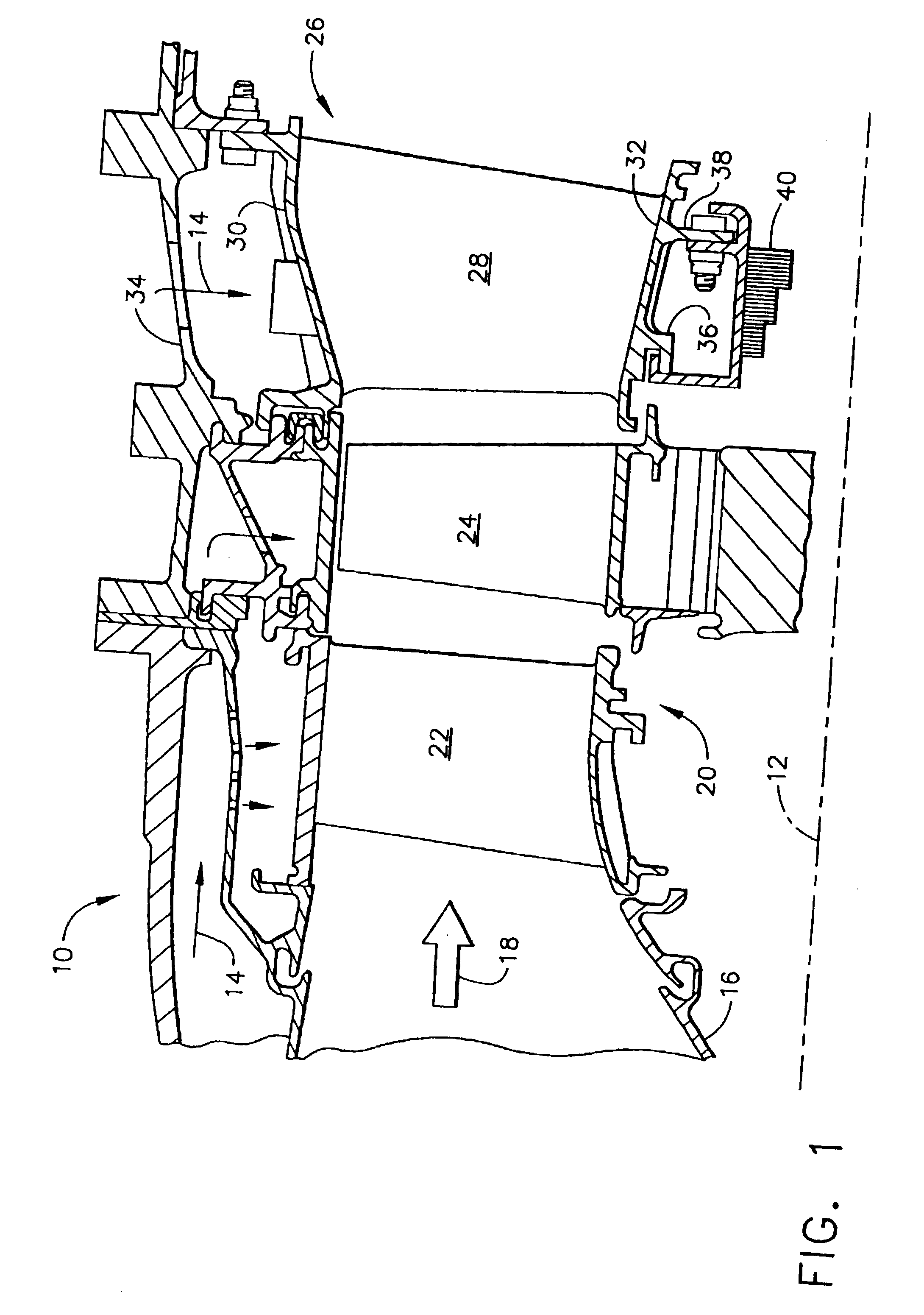
[0023]Illustrated in FIG. 1 is a portion of an exemplary aircraft gas turbine engine 10 which is axisymmetrical about a longitudinal or axial centerline axis 12. The engine includes a fan and a multistage compressor (not shown) through which air 14 is pressurized in turn, with the fan air being used for propelling an aircraft in flight, and the air pressurized in the compressor being mixed with fuel and ignited in a combustor 16, only the aft portion thereof being illustrated, for generating hot combustion gases 18 which flow downstream therefrom.

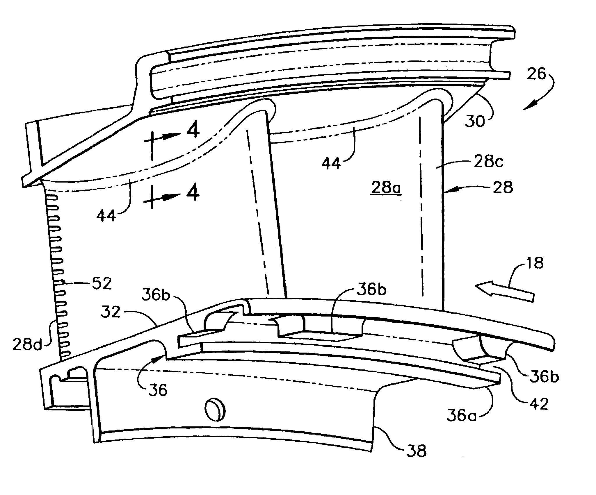
[0024]The engine includes a high pressure turbine 20 having a first stage stator nozzle 22 followed in turn by a row of first stage turbine rotor blades 24 extending radially outwardly from a supporting disk. The combustion gases 18 are channeled through the nozzle vanes 22 and blades 24 for powering the compressor in a conventional manner.

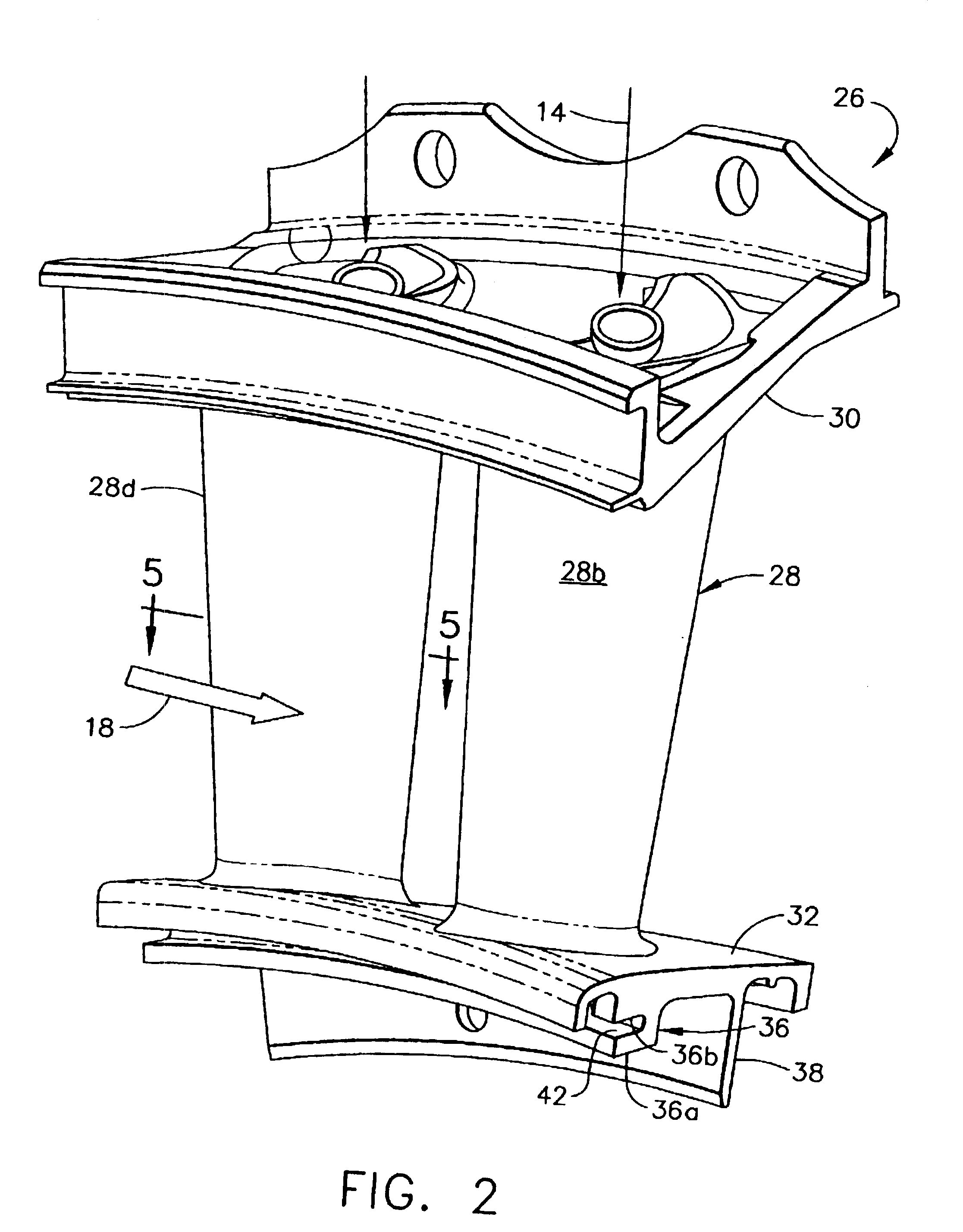
[0025]Disposed immediately downstream from the first stage blades 24 is a second stage turbine stator ...


PUM


Abstract

A turbine nozzle includes a plurality of vanes joined at opposite ends to outer and inner bands. The inner band has a forward hook which is segmented to reduce thermal mismatch. And, in additional embodiments the vane includes an impingement baffle having preferential cooling.

Description

BACKGROUND OF THE INVENTION[0001]The present invention relates generally to gas turbine engines, and, more specifically, to turbine nozzles therein.[0002]In a gas turbine engine, air is pressurized in a compressor and mixed with fuel and ignited in a combustor for generating hot combustion gases. Energy is extracted from the gases in corresponding turbine stages which power the compressor and produce useful work, such as powering a fan in a turbofan engine for propelling an aircraft in flight, for example.[0003]Since the turbines are bathed in the hot combustion gases during operation, they must be suitably cooled which is typically accomplished by bleeding a portion of the pressurized air from the compressor and channeling it through the turbine components.[0004]A high pressure turbine directly receives gases from the combustor and includes a stator nozzle and a corresponding first stage rotor having a plurality of rotor blades extending radially outwardly from a supporting disk. A...

Claims


Application Information

Patent Timeline
IPC IPC(8): F01D9/04F01D9/02F01D5/18
CPCF01D5/189F01D9/042Y02T50/60
Inventor TRESSLER, JUDD DODGENICHOLS, GLENN H.
Owner GENERAL ELECTRIC CO
Why Eureka
Eureka Blog
Learn More