Electric power system protection and control system

a technology for power systems and control terminals, applied in the direction of audible advertising, parameter calibration/setting, advertising, etc., can solve the problems of large amount of data handled by the cb relay correlation unit, difficult to correlate accurately, and large discrepancy, so as to facilitate and rapid relay operation state change, the effect of cb operation state chang

Inactive Publication Date: 2008-01-29
KK TOSHIBA
View PDF5 Cites 2 Cited by
  • Summary
  • Abstract
  • Description
  • Claims
  • Application Information

AI Technical Summary

Benefits of technology

[0100]It is an object of the present invention to provide a system which performs correlation processing of CB operation state change and relay operation state change easily and rapidly without employing a CB relay correlation database.

Problems solved by technology

Therefore, there is a possibility of considerable discrepancy between the time-point of relay operation state change detection and the time-point of CB operation state change detection, or the order of these could be reversed.
It is difficult to correlate accurately and rapidly the CB operation state changes and relay operation state changes that caused them.
Therefore, the amount of data that is handled by the CB relay correlation unit is extremely large and the correlation algorithm is also complicated.
But, a large number of state change data (the state change data of all the protection and control terminals) has to be correlated with any given CB state change data, so an enormous time is required for the correlation processing.
In particular, although the amount of state change data that needs to be handled by the CB relay correlation unit depends on the maximum time T1 of the discrepancy between the time-point of detection of relay operation state change and the time-point of detection of CB operation state change, supposing that the maximum value T1 of the discrepancy time is wrongly selected, this T1 being set too short, there is a high risk of correlation overflow or a risk of occurrence of display less of the relays operated in response to the CB operation state change.
On the other hand, if, in order to avoid display less of the relays operated in response to CB operation state change, the maximum value T1 of the discrepancy time is set to a larger value, there is a risk that each item of CB state change data would have to be correlated with an even larger number of state change data.
It increases the correlation processing load, further increasing the correlation processing time.
This takes a large amount of time.

Method used


Image

  • Electric power system protection and control system
  • Electric power system protection and control system
  • Electric power system protection and control system

Examples


first embodiment

[0149]A power system protection and control system according to the invention is described with reference to FIG. 1-FIG. 6.

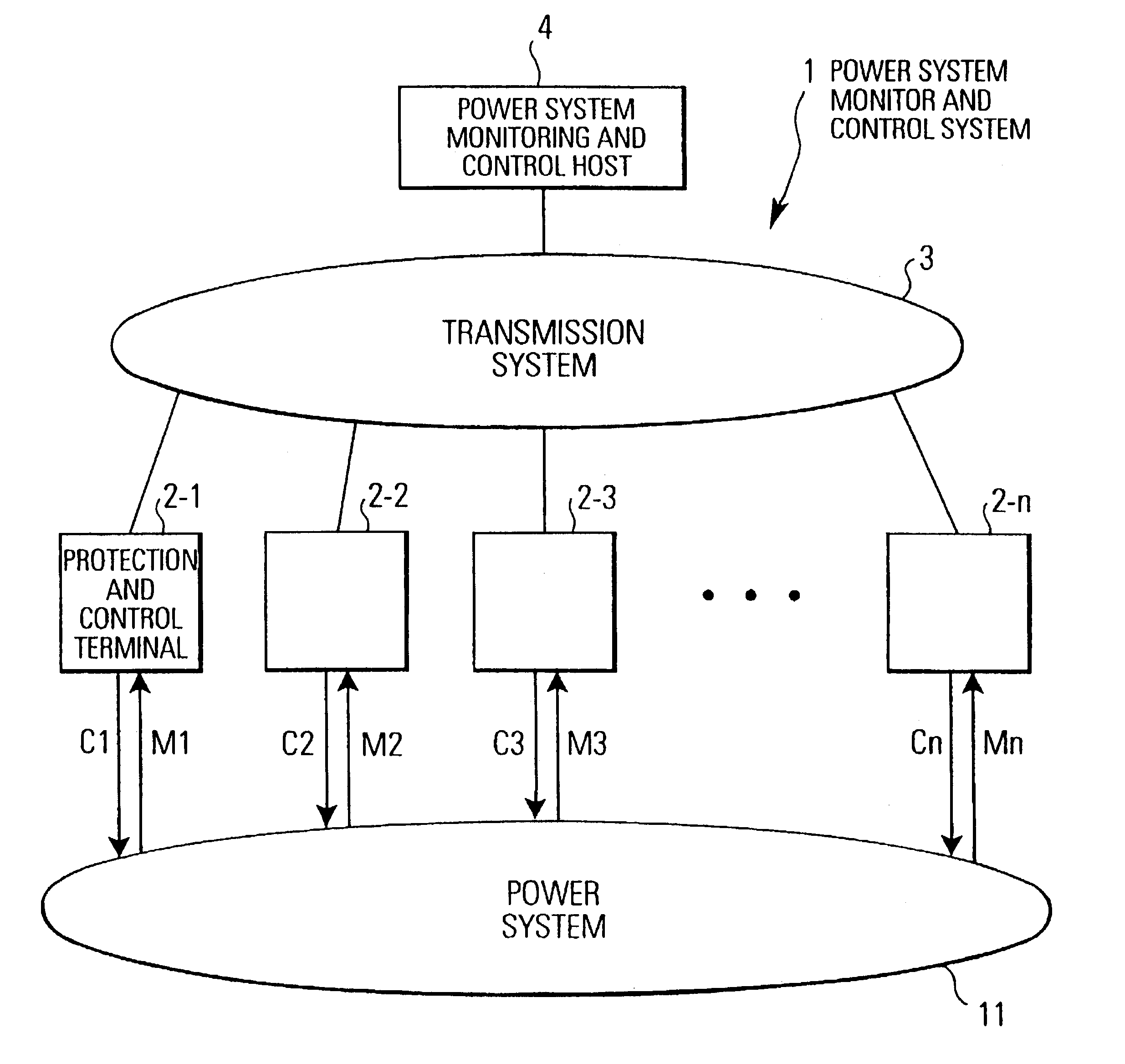
[0150]FIG. 1 shows the basic layout of a power system monitoring and control system 1 according to this embodiment.

[0151]The power system monitoring and control system 1 shown in FIG. 1 comprises a plurality of protection and control terminals 2-1-2-n.

[0152]The protection and control terminals 2-1-2-n processing performs control of the plurality of state variables (electrical quantities) M1-Mn such as current or voltage input from for example substations (substation A, substation B, substation C, . . . ) constituting a power system 11.

[0153]The protection and control terminals 2-1-2-n perform protection and control of the power system 11 by sending to the power system 11 protection and control outputs C1-C2 based on the protection and control processing result.

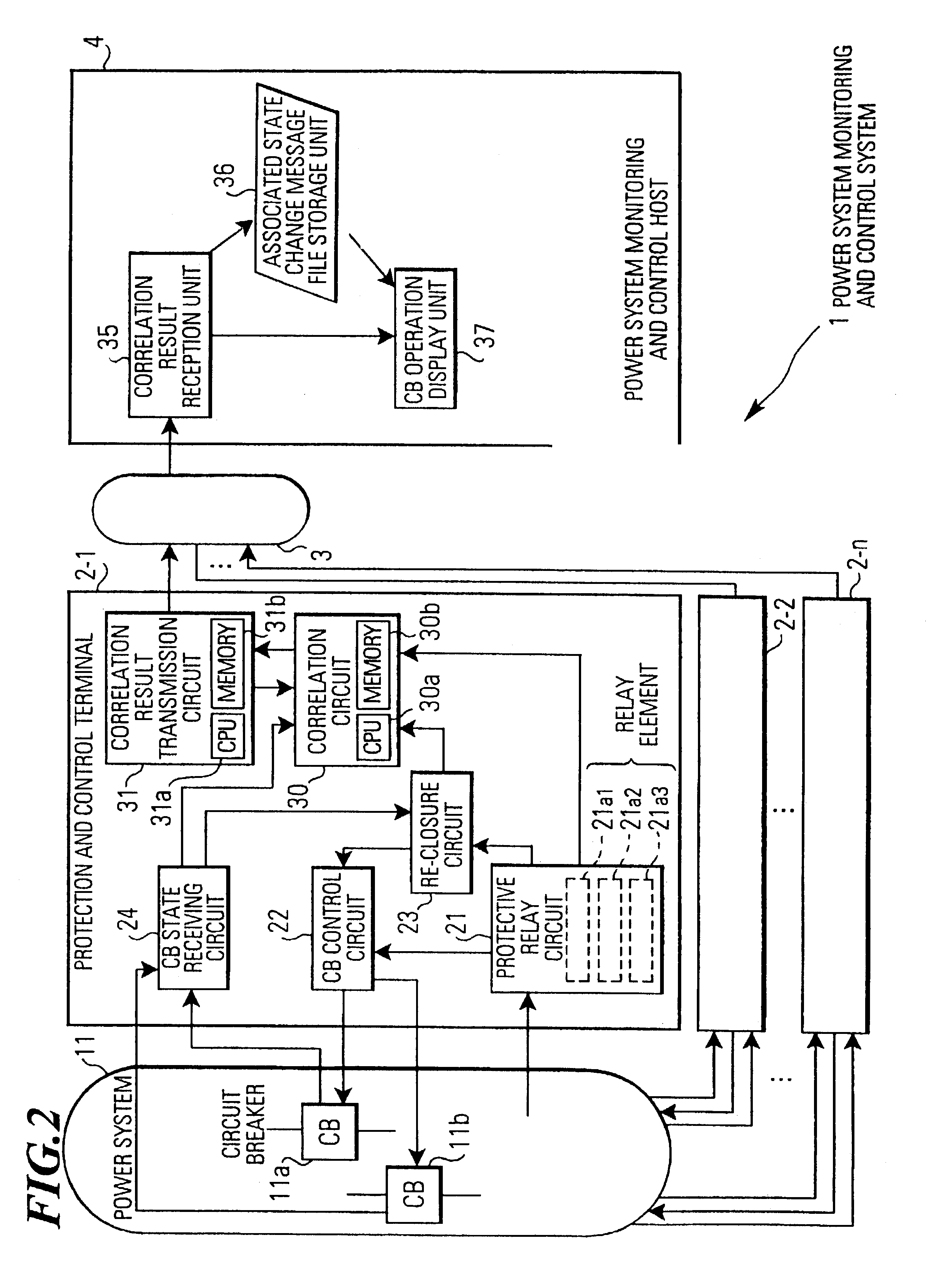
[0154]A power system monitoring and control host 4 receives data relating to the power system sent from...

second embodiment

[0224]A power system protection and control system according to the invention is described with reference to FIG. 7.

[0225]In the power system monitoring and control system 1A of this embodiment, since, apart from the processing of the CPU 30a of the correlation circuit 30 of the protection and control terminals 2-1-2-n in FIG. 2 and the processing of the CPU 31a of the correlation result transmission circuit 31 is different from those of the power system monitoring control system 1 described in the first embodiment.

[0226]Otherwise, the construction and operation of power system monitoring control system 1 illustrated in FIG. 2 is equivalent, so, in this embodiment, only the processing of a CPU 30a of a correlation circuit 30A and the processing of a CPU 31a of a correlation result transmission circuit 31A will be described, the rest of the description thereof being omitted.

[0227]In addition to operation processing in accordance with the algorithm shown in previous FIG. 3, the CPU 30...

third embodiment

[0250]A power system protection and control system according to the invention is described with reference to FIG. 8.

[0251]In a power system monitoring and control system 1B of this embodiment, the processing of a CPU 30a of a correlation circuit 30 of the protection and control terminals 2-1-2-n in FIG. 2 and the processing of a CPU 31a of a correlation result transmission circuit 31 are different from those of the power system monitoring control system 1 described in the first embodiment, but the layout and operation are otherwise identical with those of power system monitoring and control system 1 shown in FIG. 2.

[0252]Therefore, in this embodiment, the processing of the CPU 30a of the correlation circuit 30B and the processing of the CPU 31a of the correlation result transmission circuit 31B only will be described, the rest of the description being omitted.

[0253]The CPU 30a of the correlation circuit 30B of this embodiment, in addition to the operation processing in accordance wi...


PUM


Abstract

A Power system protection and control system has protection and control terminals that perform protection and control of a power system by operation of a plurality of CBs in response to state variables input from power system; and a power system monitoring and control host mutually connected in a fashion to permit data exchange through a transmission system (communication network) with protection and control terminals and that performs monitoring and control of power system in accordance with data transmitted from protection and control terminals. Protection and control terminals each has a correlation circuit that performs correlation of an operated CB and the cause of its operation, using information sent from protective relay circuit, CB control circuit, re-closure circuit and CB state receiving circuit when at least one of a plurality of CBs is operated, and a correlation result transmission circuit that transmits the result obtained by the correlation processing of this correlation circuit to power system monitoring and control host through transmission system. The power system monitoring and control host includes a correlation result transmission unit that receives and displays the correlation result transmitted through transmission system from correlation result transmission circuit, associated message file storage unit and CB operation display unit.

Description

FIELD OF THE INVENTION[0001]The invention relates to a power system protection and control terminal for protection and control of a power system by operating switches such as circuit breakers in response to state variables input from the power system, a power system monitoring and control system, and a storage medium in which a program is stored.[0002]In particular, the storage medium relates to a power system protection and control terminal equipped with a function for performing correlation processing of a protective relay and, a switch operation, a power system monitoring control system and a storage medium for storing a program.DESCRIPTION OF THE RELATED ART[0003]A power system monitoring and control system has a plurality of protection and control terminals arranged, for example, corresponding to each substation constituting the power system and that perform protection and control of the power system in accordance with state variables such as currents or voltages obtained from ...

Claims


Application Information

Patent Timeline
Patent Type & Authority Patents(United States)
IPC IPC(8): G08B21/00H02H3/00H02H7/26H02H3/02H02J13/00
CPCH02H3/006H02H7/261H02H3/04
Inventor HASEGAWA, OSAMUSHIROTA, YOSHIHIROKAINO, YASUO
Owner KK TOSHIBA
Why Eureka
Try Eureka