Tufting machine yarn feed pattern control
- Summary
- Abstract
- Description
- Claims
- Application Information
AI Technical Summary
Benefits of technology
Problems solved by technology
Method used
Image
Examples
Embodiment Construction
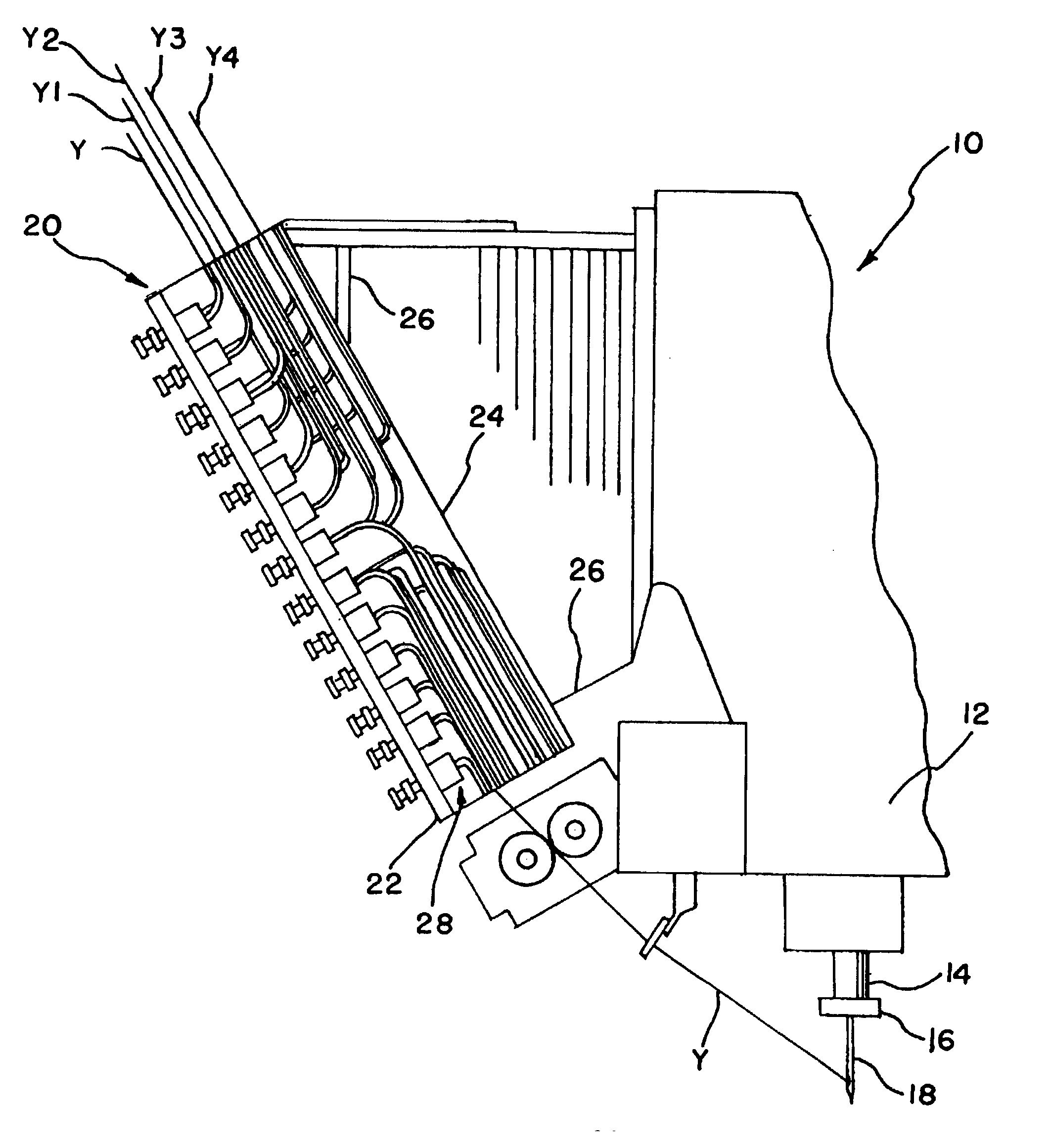
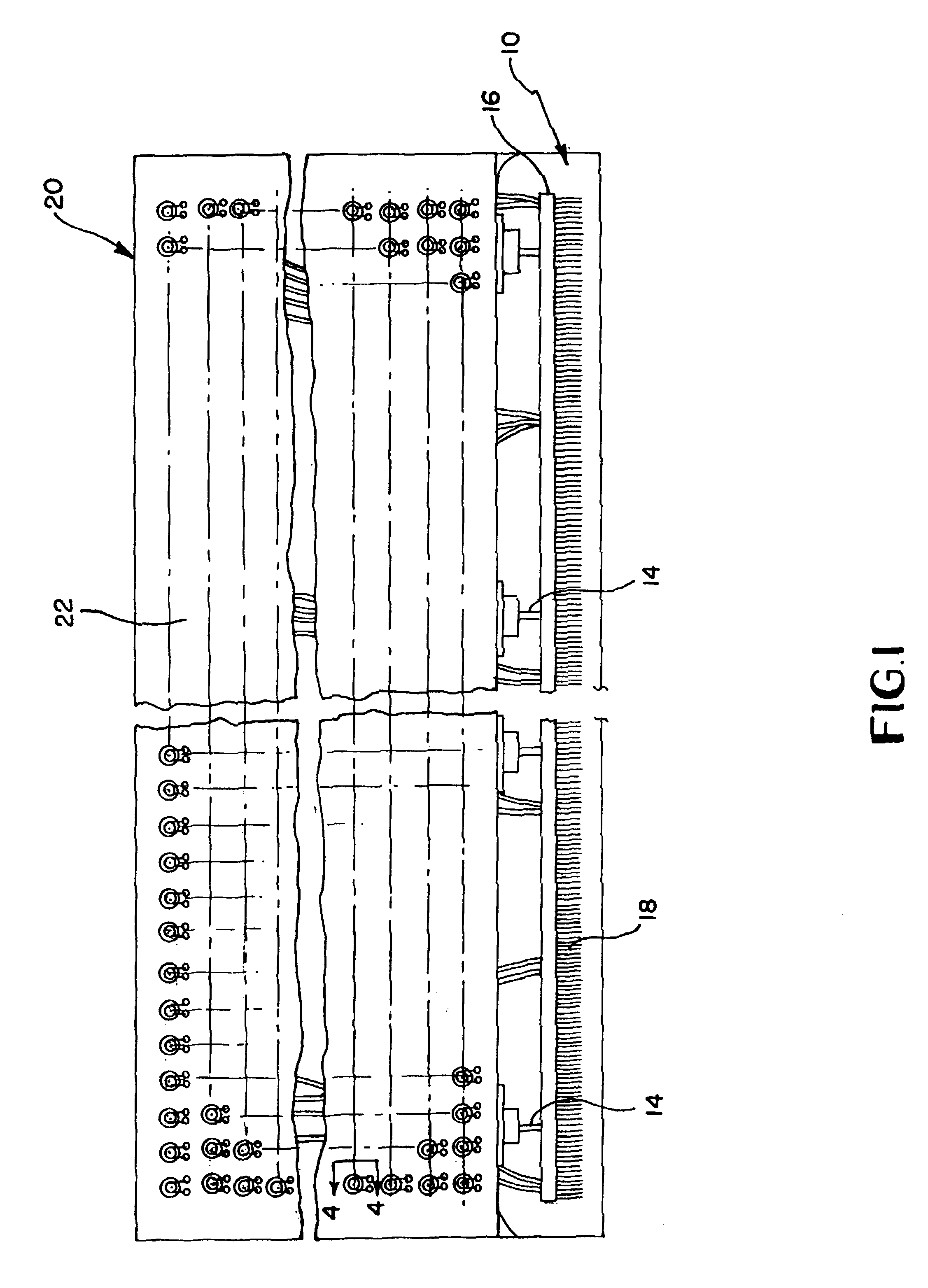
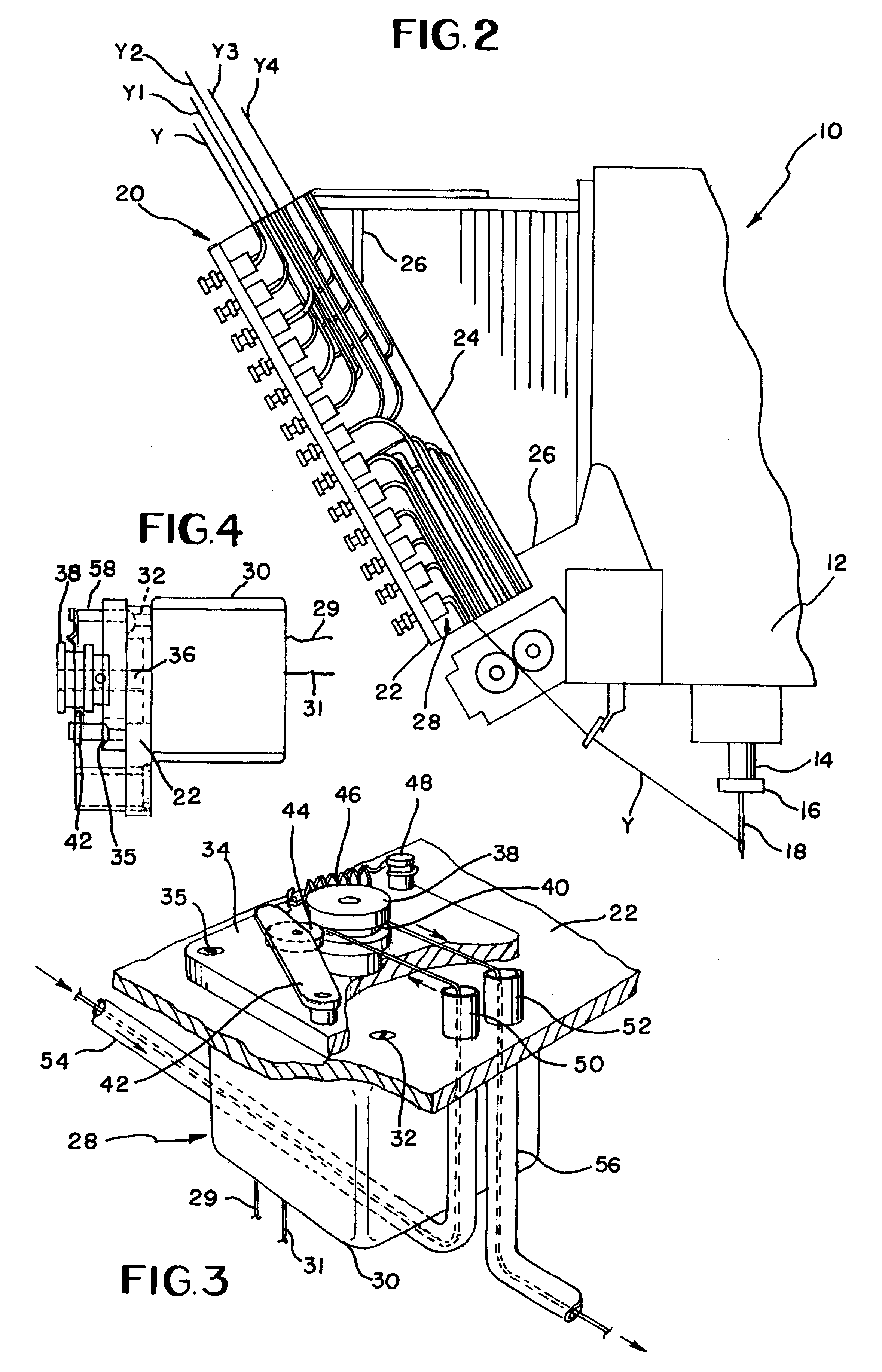
[0016]Referring to the drawings, FIGS. 1 and 2 illustrate a tufting machine 10 having a head 12 in which a plurality of transversely spaced push rods 14 is reciprocally mounted, the push rods carrying a needle bar 16 at the lower ends thereof. The needle bar 16 carries a multiplicity of needles 18, which may be mounted in a single roll as illustrated or in two rows which may or may not be staggered relative to each other as well known in the art. Moreover, rather than being a laterally fix needle bar, the needle bar 16 may be of the laterally shiftable types as is well known in the art. In any event, the needles cooperate with corresponding respective loopers and hooks (not illustrated) conventionally mounted beneath the head as is notoriously well known in the art.
[0017]Mounted as an attachment on the head of the tufting machine is a yarn feed roller pattern assembly 20 constructed in accordance with the present invention. Yarn, such as yarn strands Y, Y1, Y2, Y3, Y4, are supplied ...
PUM
 Abstract
Description
Claims
Application Information
 - R&D
- Intellectual Property
- Life Sciences
- Materials
- Tech Scout
- Unparalleled Data Quality
- Higher Quality Content
- 60% Fewer Hallucinations
Browse by: Latest US Patents, China's latest patents, Technical Efficacy Thesaurus, Application Domain, Technology Topic, Popular Technical Reports.
© 2025 PatSnap. All rights reserved.Legal|Privacy policy|Modern Slavery Act Transparency Statement|Sitemap|About US| Contact US: help@patsnap.com


