Electronic watch

a technology of electronic watch and stepping motor, applied in the direction of generating/distributing signals, dynamo-electric converter control, horology, etc., can solve the problems of magnetic interference with the other stepping motor, particularly and difficult to achieve normal operation at a low voltag

Inactive Publication Date: 2008-06-10
CITIZEN WATCH CO LTD
View PDF15 Cites 16 Cited by
  • Summary
  • Abstract
  • Description
  • Claims
  • Application Information

AI Technical Summary

Benefits of technology

[0119]That is, in an electronic watch according to the present invention in supplying a prescribed drive pulse to an appropriate drive motor via the drive circuit control means so as to cause the execution by the above-noted drive motor of a prescribed display operation, in addition to monitoring the control mode which is currently being executed by the drive circuit control means, in the case in which, in this control mode, because of a change in the drive voltage of the power supply or a change in another condition, a condition occurs in which the reliability with regard to a prescribed display operation of the drive ...

Problems solved by technology

However, the reverse rotation operation of the above-noted stepping motor exhibits a narrower range of operating voltage than for forward operation, and it is particularly difficult to achieve normal operation at a low voltage.
Additionally, because the drive frequency for fast forward drive is high, the pulse width must be made narrow, making normal operation at a low voltage difficult.
Thus, when one stepping motor rotates, it magnetically interferes with the other stepping motor.
In a motor such as the first stepping motor, in which detection is made of rotation and non-rotation, the above-noted magnetic interference can result in a misjudgment that the first stepping motor has rotated, when in fact it has not rotated, thereby resulting in inhibiting of the output of the compensation drive pulse, this resulting in a disturbance of the timekeeping by the watch.
Thus, although the first stepping motor has not actually rotated, an erroneous detection to the effect that it did not rotate occurs, and a compensation drive pulse Ph is not output as a result.
Thus, at a low voltage at which drive is not possible, drive is only possible at a power supply voltage Vc of 2.6 V or greater.
However, at a high power supply voltage Vc, the normal pulse Ps8 has more drive capacity than is necessary, so that the power consumption beco...

Method used


Image

  • Electronic watch
  • Electronic watch
  • Electronic watch

Examples


Embodiment Construction

[0138]Examples of an electronic watch according to the present invention will be described in detail below, with reference being made to the appropriate accompanying drawings.

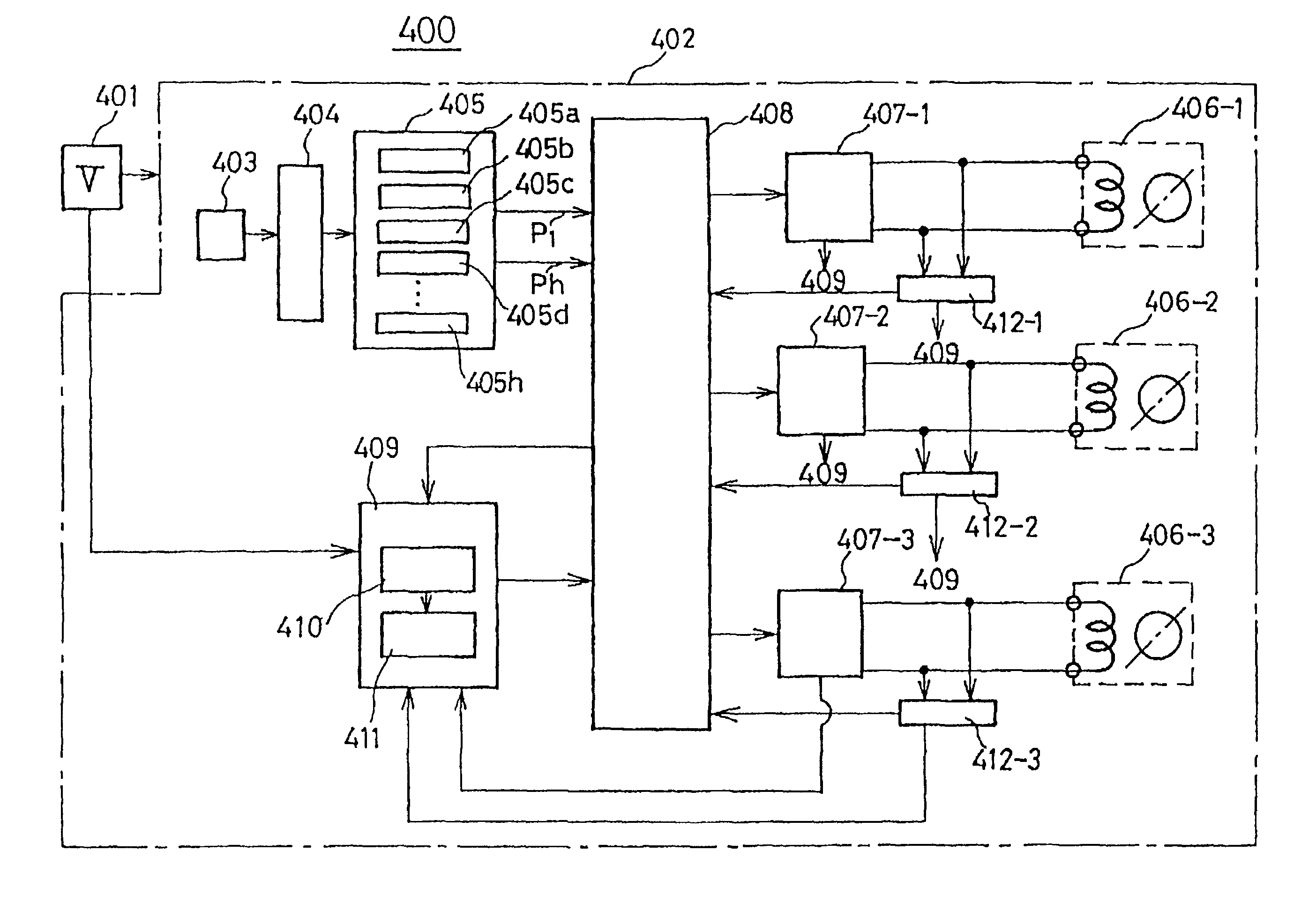
[0139]FIG. 9 is a block diagram which shows in simplified form an example of the configuration of an electronic watch 400 according to the present invention. In this drawing, the electronic watch comprises a power supply 401 and a watch circuit 402. The watch circuit 402 comprises an oscillator circuit 403, a frequency divider circuit 404, a drive pulse generation means 405, a drive motor 406 which, in response to a drive pulse P1 that is output by the above-noted drive pulse generation means 405, drives at least one of the hour / minute, second, and functional hands including chronograph hands, a drive circuit means 407 which controls the drive of the drive motor 406, a drive circuit control means 408 which controls the above-noted drive circuit means 407, and a control condition detection means 409 which is con...


PUM


Abstract

An electronic watch 400 which comprises a power supply 401 and a watch circuit 402. The watch circuit 402 comprises an oscillator circuit 403, a frequency divider circuit 404, a drive pulse generation means 405, a drive motor 406 which, in response to a drive pulse P1 that is output by the above-noted drive pulse generation means 405, drives at least one of the hour/minute, second, and functional hands including chronograph hands, a drive circuit means 407 which controls the drive of the drive motor 406, a drive circuit control means 408 which controls the above-noted drive circuit means 407, and a control condition detection means 409 which is connected to the above-noted drive circuit control means 408 and which detect the control condition in the drive circuit control means 408, the control condition detection means 409 being provided with a non-proper condition detection means 410 which senses the occurrence of a condition in which it is not possible to properly drive the above-noted drive motor 406 under a prescribed condition in a prescribed control mode currently being executed, and a control mode change-instructing means 411 which, in response to a detection signal of the above-noted non-proper condition detection means 410, issues an instruction to the drive circuit control means 408 to change the control mode currently being executed.

Description

BACKGROUND OF THE INVENTION[0001]1. Field of the Invention[0002]The present invention relates to an electronic watch, and more specifically it relates to an electronic watch having a drive motor which is driven by a normal hand-movement drive pulse and a drive motor which is driven by a non-normal hand-movement drive pulse that differs from the above-noted normal hand-movement drive pulse, so that even if the power supply voltage or drive conditions change, a proper drive condition is maintained for the drive motor which is driven by a normal hand-movement drive pulse, and which can also achieve low-power-consumption operation[0003]2. Description of the Related Art[0004]There is a usual type of stepping motor for an electronic watch rotates in the forward direction only in response to, for example, an input signal, and is configured so as not to rotate in the reverse direction.[0005]For this reason, if it is desirable to cause the rotor to rotate in the reverse direction, for exampl...

Claims


Application Information

Patent Timeline
IPC IPC(8): G04F5/00G04C3/14G05B19/40G06F1/04H02P8/00
CPCG04C3/143G04C3/146
Inventor SATO, KOICHIKANNO, FUMIO
Owner CITIZEN WATCH CO LTD
Why Eureka
Try Eureka