300 mm microenvironment pod with door on side

a microenvironment pod and door technology, applied in the field of packaging, can solve the problems of only compounding problems, difficult to design a suitable package, and high cost of suitable packaging for use in connection with storage and transportation of wafers, and achieve the effects of high efficiency, easy cleaning, and reusable packaging

Inactive Publication Date: 2010-04-20
ENTEGRIS INC
View PDF31 Cites 1 Cited by
  • Summary
  • Abstract
  • Description
  • Claims
  • Application Information

AI Technical Summary

Benefits of technology

[0010]Suitable containers for use with wafers, photomasks, memory disks, liquid crystal display panels and flat panel displays must meet several important design criteria. They must be light weight to make manual and robotic handling tasks easier. The internal volume of the container should be minimized to reduce storage space requirement and increase storage density. The height of the container should be minimized to allow for improved stacking of the containers. The amount of polymer surface area surrounding the items during transport and storage should be minimized to reduce inorganic and organic contaminants as well as the negative affects of outgassing of the polymer.
[0011]Containers built in accordance with the present invention meet the design criteria set forth above. Such containers also provide several other unique advantages. First, tolerance build-up is minimized by means of locating the container about item center lines, thereby increasing the positional accuracy of the items stored in such containers. This enhances effective insertion and removal of the items from the container using robotic equipment. Second, the containers reduce the risk of damage caused by static electricity. This is achieved in one preferred embodiment by providing a conductive path to ground from static dissipative internal item supports to the container's external kinematic coupling plate which is used to position the container on various pieces of equipment. Third, the containers of the present invention are designed to be wet-cleaned with or without disassembly. Fourth, since the containers of the present invention can have an integral design which does not require a separate carrier, the containers can remain associated with a specific lot of items. This enables workers in the factory to better track a lot and, therefore, reduces the chance of processing errors. Fifth, the integral design, by eliminating the need for a separate cassette, minimizes the number of packaging components required to be kept in inventory and the space such components take up. Sixth, the integral design eliminates the need to accurately position a removable cassette in the container and lock it in place. Finally, the integral design can be manufactured using fewer and smaller parts, thereby reducing manufacturing costs.
[0012]It is therefore an object of the present invention to provide an isolation container which will provide protection against contamination by particles or moisture.

Problems solved by technology

This combination of problems makes designing a suitable package very difficult.
Such problems are only compounded by the environment in which such packages are typically used.
Suitable packaging for use in connection with the storage and transport of wafers, memory disks, photomasks, liquid crystal display panels and flat panel displays tend to be very expensive.
While such package designs have proven to be highly effective in conjunction with smaller items, the designs, for a variety of reasons, are not suitable for storage and transport of items having outside dimensions in the range of 300 mm or more.

Method used


Image

  • 300 mm microenvironment pod with door on side
  • 300 mm microenvironment pod with door on side
  • 300 mm microenvironment pod with door on side

Examples


Embodiment Construction

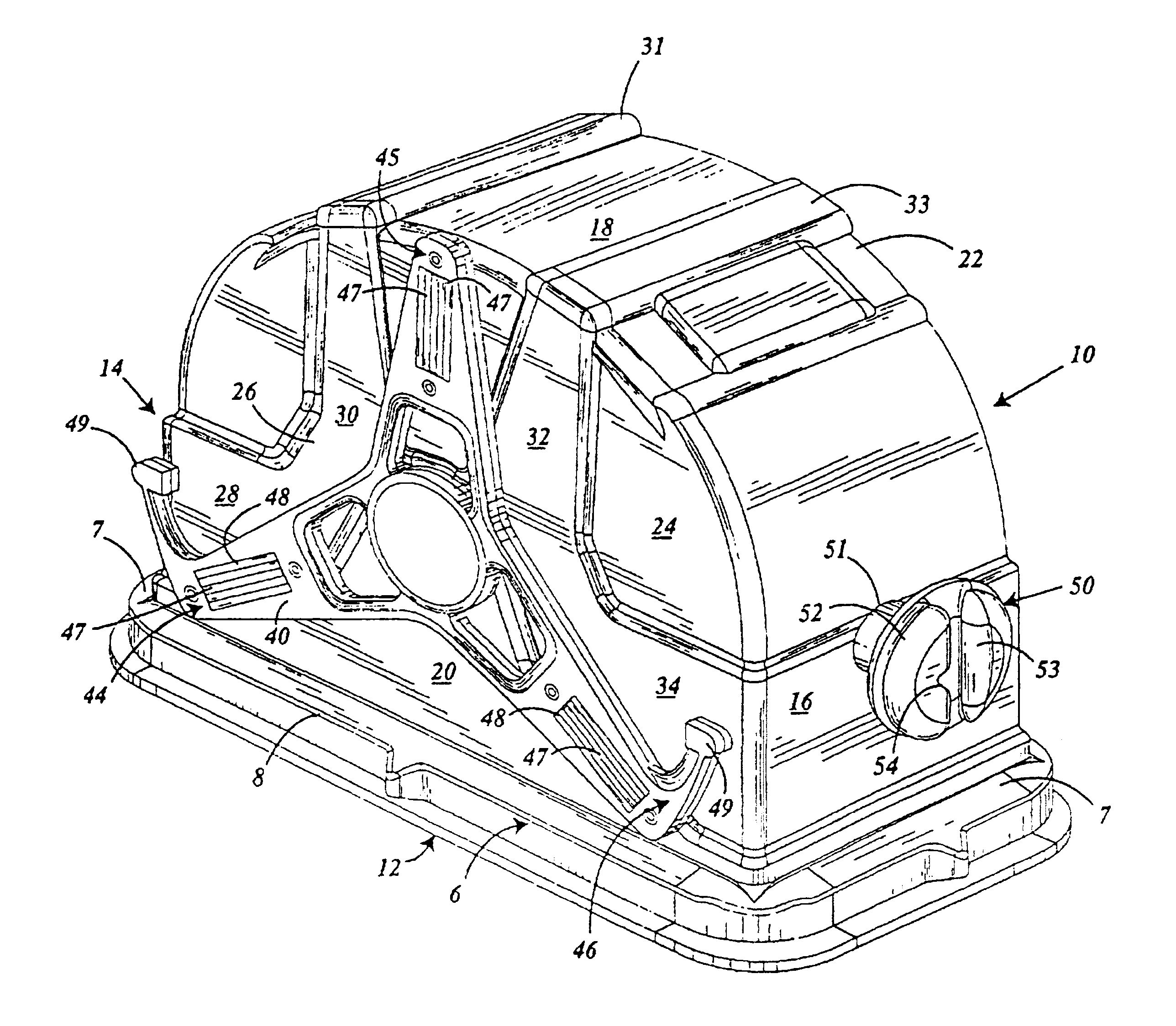
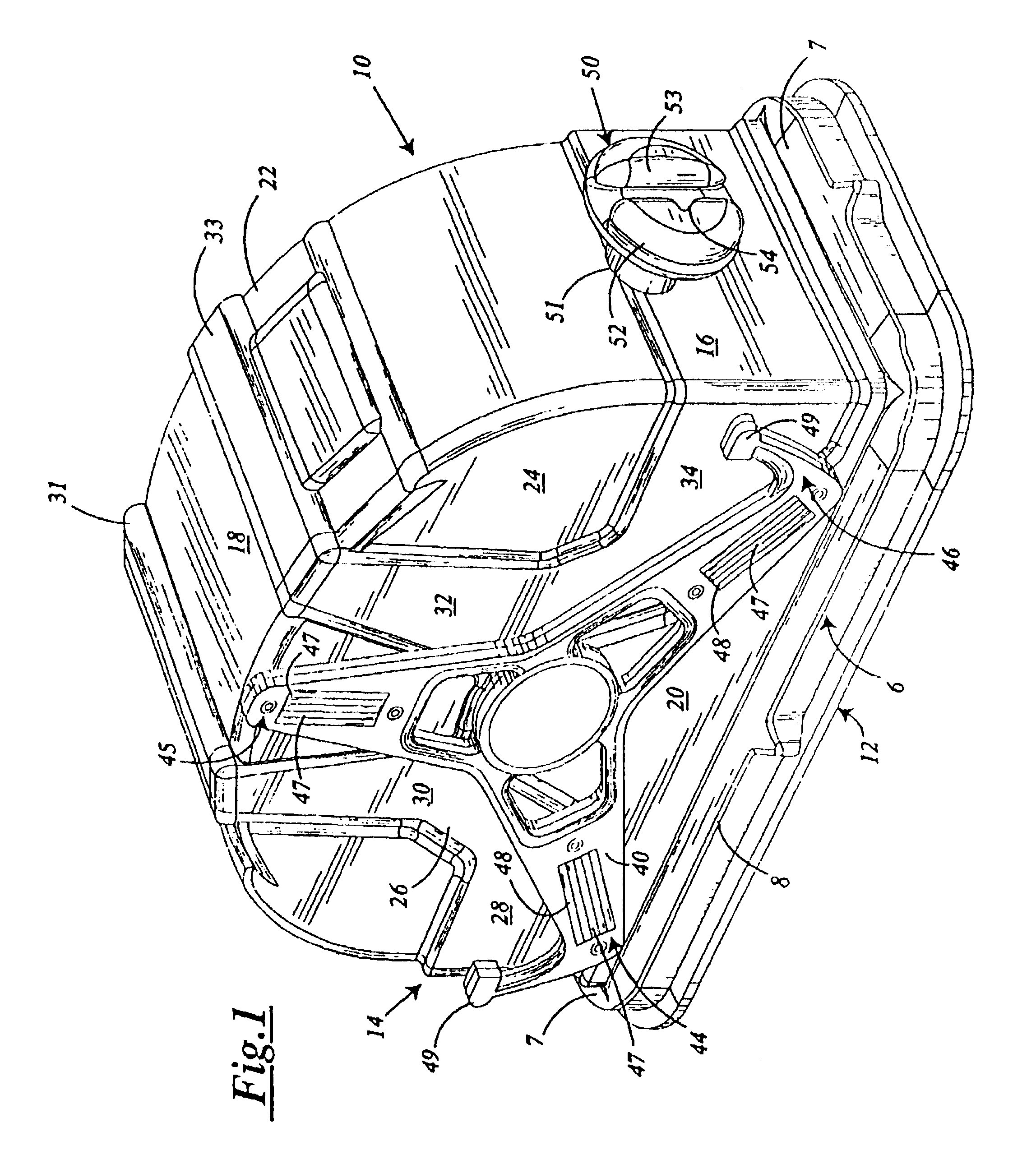
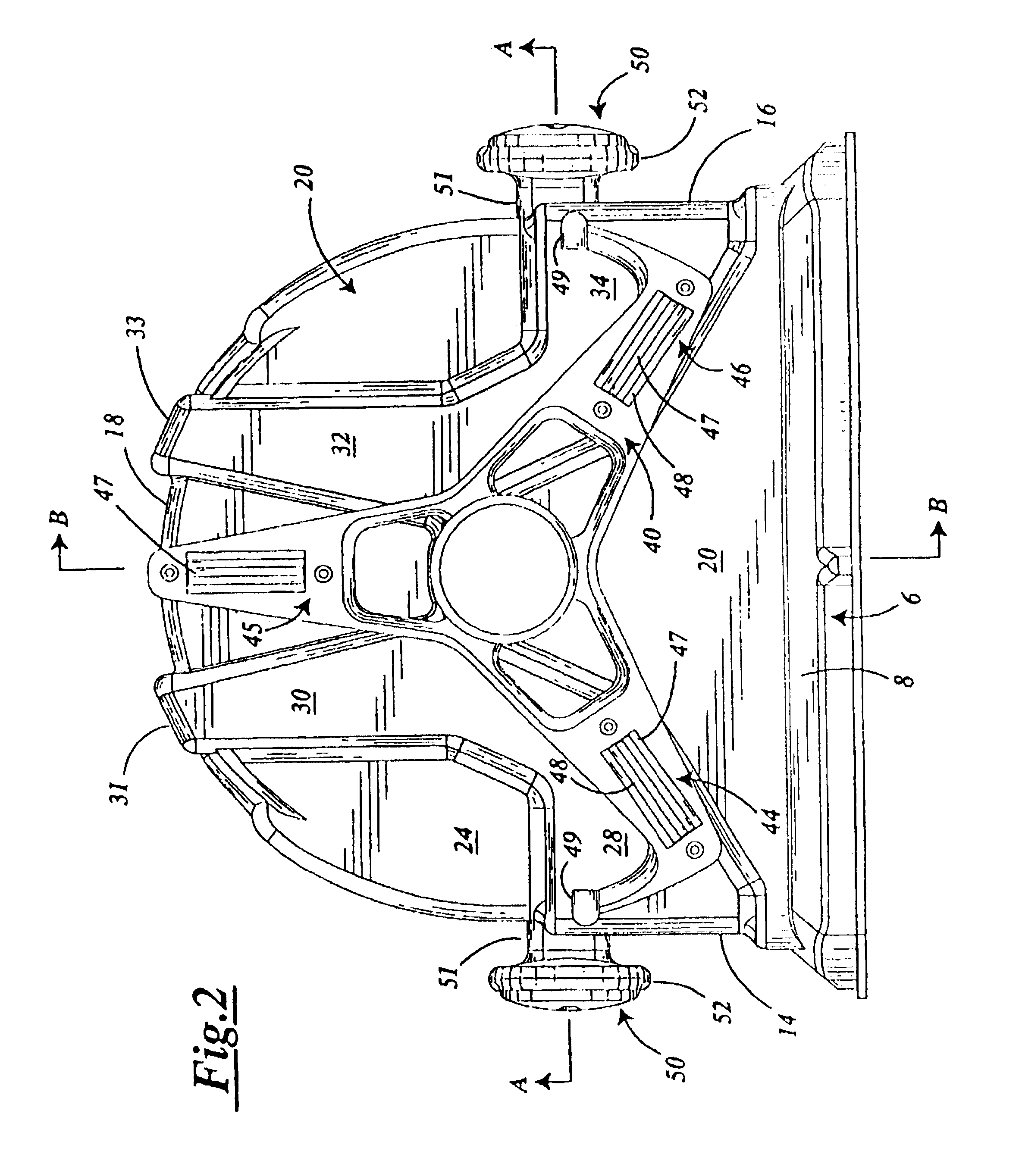
[0037]As shown in FIG. 1, the container of the present invention has an exterior shell 10. The exterior shell 10 has six sides 12, 14, 16, 18, 20 and 22.

[0038]Side 12 comprises a door frame 6 having a pair of opposing end portions 7 and a pair of side portions 8. Sides 14 and 16 of the exterior shell 10 are defined generally by straight walls extending from the opposite end portions 7 of the door frame 6. Wall 18 extends between walls 14 and 16 and is in the shape of a partial cylinder. The radius of curvature of wall 18 is generally the same as the radius of curvature of the wafer to be stored in the container. Top and bottom walls 20 and 22 complete the shell. Walls 20 and 22 have a generally flat surface 24 and a reinforcement member 26 projecting outwardly from the flat surface 24. Reinforcement member 26 prevents warpage of the container and especially walls 20 and 22. Reinforcement members 26 have four legs 28, 30, 32 and 34. Extending across wall 18 between the two legs 30 is...


PUM

PropertyMeasurementUnit
electrical chargeaaaaaaaaaa
electrical pathaaaaaaaaaa
gravityaaaaaaaaaa

Abstract

A container for creating a microenvironment is disclosed. The container includes a shell, a door and a plurality of supports having a unique design which are used to securely retain items, such as silicon wafers, in a spaced apart parallel relationship. The supports are removable. An electrical path is provided to ground the supports. Kinematic coupling structures are also provided for positioning the container on a surface so as to, for example, properly align the door with the port of a wafer processing tool.

Description

[0001]Notice: More than one reissue application has been filed for the reissue of U.S. Pat. No. 5,944,194. The reissue applications are application Ser. No. 10 / 310,069 (the present application), which is a continuation of application Ser. No. 09 / 943,098, now issued as U.S. Reissue Pat. No. RE38,221, and application Ser. No. 11 / 351,214, which is a continuation of the present application, all of which are reissues of U.S. Pat. No. 5,944,194.<?insert-end id="INS-S-00001" ?>BACKGROUND OF THE INVENTION[0002]I. Field of the Invention[0003]The present invention relates generally to a package for an item. More particularly, the present invention relates to a package specifically designed to isolate from contamination materials used in the manufacture of electronic semiconductor components and circuits. Such packages are particularly well suited for substrates, wafers, memory disks, photomasks, flat panel displays, liquid crystal displays, and the like.[0004]II. Description of the Prio...

Claims


Application Information

Patent Timeline
Patent Type & Authority Patents(United States)
IPC IPC(8): B65D85/90B65D85/48B65DG11B33/04G11B33/14H01L21/673H01L21/677
CPCH01L21/67369H01L21/67379H01L21/67383H01L21/67396G11B33/0405G11B33/14H01L21/67763B65D85/48
Inventor GREGERSON, BARRYGALLAGHER, GARYWISEMAN, BRIAN
Owner ENTEGRIS INC
Why Eureka
Try Eureka