Water safety and survival system

a technology of water safety and survival system, applied in the field of water safety gear, can solve the problems of life-threatening righting moment, unacceptable amount of pressure applied to the thorax of the wearer, etc., and achieve the effects of reducing bulk when deflated, improving appearance, and reducing cos

Inactive Publication Date: 2011-02-15
TREBOR IND
View PDF10 Cites 4 Cited by
  • Summary
  • Abstract
  • Description
  • Claims
  • Application Information

AI Technical Summary

Benefits of technology

[0023]The smallest safety vest that reliably protects the victim's airway is ideal because of its lower cost, reduced bulk when deflated, and improved appearance, all factors that contribute to compliance with use, the true basis of success in any emergency. The current water safety vest distinguishes the two critical points of buoyancy, one behind the neck and head with the second point of buoyancy being in the area of the umbilicus, and one of ballast, behind the victim and their flotation chamber. A very small amount of buoyancy and ballast securely attached to the victim at these two points is sufficient to roll an individual over and put them on their back, thereby protecting their airway from submersion. Entry and adjustments are from below, from the side or if from the front then the front chamber must overlap and be maintained and secured in a central position. Only this combination of small buoyant chambers reliably creates safe positioning of the victim's neck and head. This face up righting moment is generated regardless of the angle of entry into the water or level of conscious participation. This strong righting moment also compensates for the ongoing effects of rotational forces such as waves that at a certain point will overcome the lateral stabilization provided by the rear perimeter chamber.
[0024]Ideally the rear chamber is constructed to cradle the head and neck preventing it from drooping over backwards or sideways and becoming submerged. The chamber can be extended along the sides where they act much as outriggers, stabilizing the body from being rolled over because of wave action. The perimeter rear buoyant chamber defines a space, and actually forms a containment means for stowing a separating flotation chamber, such as a multi-function rescue safety product. It also is the ideal site of expansion that occurs when an inflatable life vest is actually inflated. All inflatable buoyant chambers upon inflation convert from a two dimensional product to a space occupying three dimensional object. This creates a shortening that results in constriction. Power inflated vests generally have an over pressure valve to protect against rupture but before this is actuated an unacceptable amount of pressure is applied to the thorax of the wearer. To compensate for this either the garment is very loose so that when it is inflated the wearer can still breathe or the chamber slides along a retaining strap or belt shifting the position of the inflatable bladder and thereby shifting the righting moment. Current inflatable vests upon inflation slide to the rear as an accommodation to the front entry. This pulls the buoyant means towards the back and results in greater moments of stability in the side high position winch submerges the airway. In the current embodiment if the vest is entered from the front its closure is fixed. The rear buoyant chamber upon inflation stretches away from the center of the back and out towards the sides strengthening the lateral stability of the vest and the forward central buoyant bubble remains aligned along the center.

Problems solved by technology

This creates a shortening that results in constriction.
Power inflated vests generally have an over pressure valve to protect against rupture but before this is actuated an unacceptable amount of pressure is applied to the thorax of the wearer.
If the front chamber is too wide, it can combine with the rear buoyant bladder and create a second, life threatening righting moment in which either side could be held at the surface and concomitantly the airway submerged.

Method used


Image

  • Water safety and survival system
  • Water safety and survival system
  • Water safety and survival system

Examples


Embodiment Construction

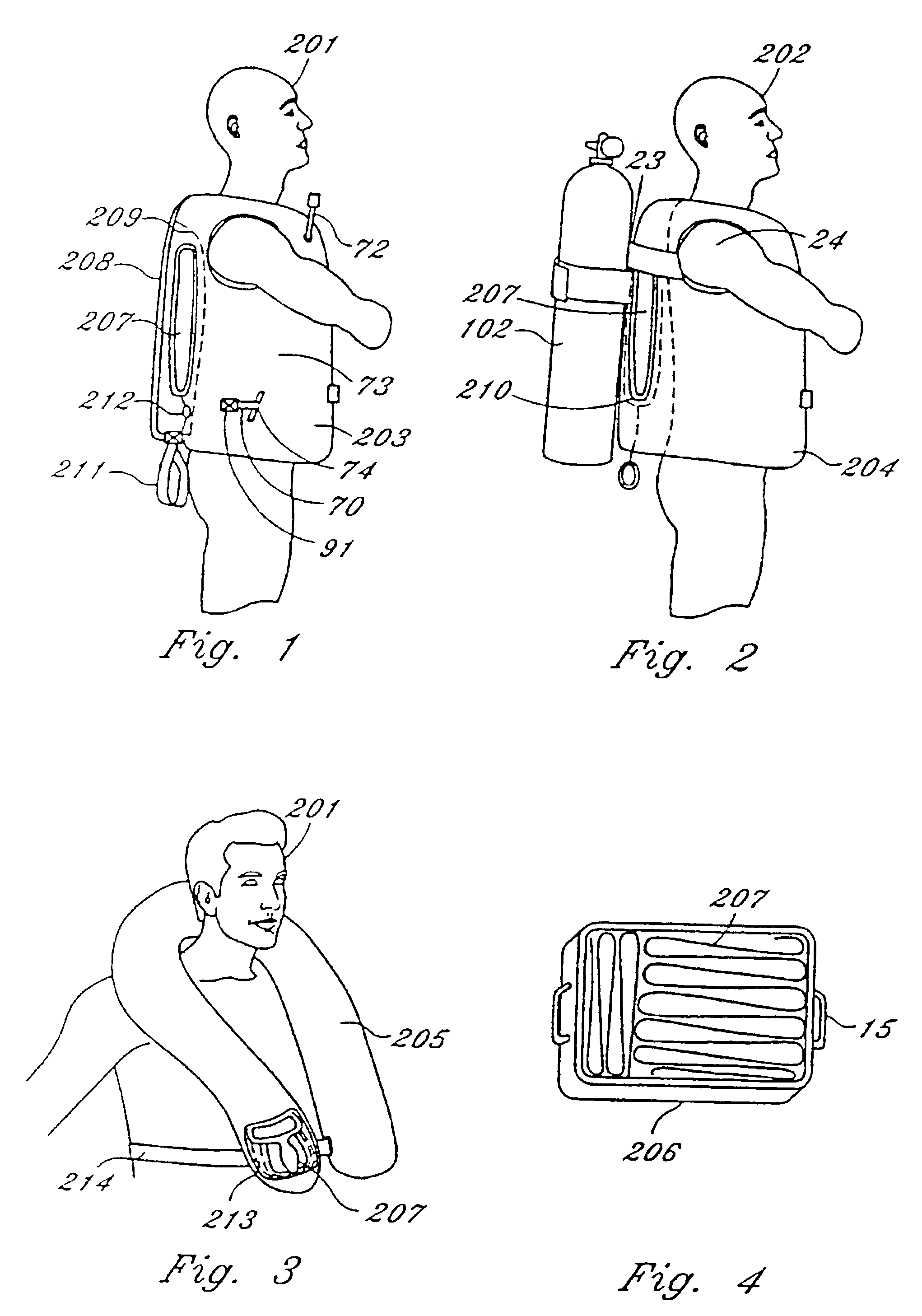
[0104]FIG. 1 shows victim 201 wearing a vest 203 that can function separately as a snorkeling vest, personal flotation device for boating or alternately hooked up to the primary bladder of a buoyancy compensator through quick release means 91 and hose 70 that is attached within pocket 74. Vest 203 can also be inflated through oral inflation means 72. Additionally, vest 203 can be incorporated with a ballast means 100 (FIG. 48). A multi-function rescue product and raft 207 is stowed within the back pocket of the lift vest between the outer wall 208 and inner wall 209. A retrieval strap 211 opens the pouch formed by wall 208 and wall 209, and is wrapped around raft 207 allowing the user to remove rescue product and raft 207, comprised of an expansible material allowing inflation chamber portion 73 located along the perimeter of the back to roll forward upon inflation.

[0105]FIG. 2 shows a diver 202 adapting an existing vest style buoyancy compensator 204 to carry the rescue product 207...


PUM


Abstract

A counterweight assembly is provided to enhance heads up surface positioning of a person. The assembly includes a weight / ballast member strategically disposed on a cylinder / tank worn by a diver during a dive. The weight member can be attached by several different embodiments. Preferably, the weight member is attached such that the diver cannot release or adjust the weight member while he or she is diving. The weight member rotates the person to ensure heads up surface positioning in the event the person becomes incapacitated. Also provided are several other water safety and survival devices.

Description

[0001]This Application is a divisional of U.S. patent application Ser. No. 08 / 645,206, filed May 13, 1996, now U.S. Pat No. 5,855,454 which is a continuation-in-part of U.S. patent application Ser. No. 08 / 149,137, filed Nov. 8, 1993, now U.S. Pat. No. 5,516,233, which is a continuation of U.S. patent application Ser. No. 07 / 870,244, filed Apr. 17, 1992, now abandoned.BACKGROUND OF THE INVENTION[0002]1. Field of the Invention[0003]The present invention relates to water safety gear including life vests, integrated rescue products, and hypothermic protective gear, adapted for one-time use by the victim placed in the water by accident or for regular use by the water enthusiast whether a sailor or scuba diver.[0004]2. Description of the Prior Art[0005]Heretofore, accidental immersion often resulted in death by two causes, aspiration leading to asphyxiation or hypothermia. A life saving system, to be viable for more than a few minutes, must successfully address both of these issues. Curre...

Claims


Application Information

Patent Timeline
Patent Type & Authority Patents(United States)
IPC IPC(8): B63C11/02B63C9/125B63C11/08B63C11/30
CPCB63C9/1255B63C9/1055B63C9/155B63C11/2245B63C11/30B63C2011/306
Inventor COURTNEY, WILLIAM L.CARMICHAEL, ROBERT M.
Owner TREBOR IND
Why Eureka
Try Eureka