
Flexible material

a flexible material and manufacturing method technology, applied in the direction of lamination, magnetic recording, protective equipment, etc., can solve the problems of restricting limiting the movement of the wearer, and expensive or inconvenient supply of different sizes

Inactive Publication Date: 2012-06-05
STIRLING MOLDINGS 2016 LTD
View PDF116 Cites 22 Cited by
  • Summary
  • Abstract
  • Description
  • Claims
  • Application Information

AI Technical Summary

Benefits of technology

[0013]It is an object of the present invention to overcome, or at least reduce, the problems associated with the manufacture of conventional protective material and with protective wear made therefrom.
[0017]Such a flexible material can confirm more easily to the body of the wearer than conventional materials, as it is flexible in all three dimensions. It is therefore more comfortable to wear and can accommodate movement better than conventional materials. When used as a protective material or to form protective wear a single size, or a reduced number of sizes, can fit many different sized bodies.
[0018]As the elements are separate and spaced apart; this facilitates flexing of the substrate to form a curved surface and enables the material to flex in all directions without “locking up” or preventing movement in a particular direction. This is a particular advantage the flexible material of the present invention has over prior art arrangements which tend not to exhibit universal flexibility.
[0021]The elements preferably take the form of blocks. They can be of regular or irregular shape, for example hexagonal or octagonal in cross-section. The elements are preferably evenly distributed on the substrate with a density of between 100 and 8000 elements / m2, more preferably between 250 and 8000 elements / m2, and still more preferably between 4000 and 6000 elements / m2. In one embodiment, the elements comprise cubes of side 12 mm spaced apart by 2 mm. This gives a density of about 5000 cubes / m2. This allows the material to flex easily along all directions, an improvement over known quilted protective materials. Also, one type of material can be cut to many different sizes, for example to form protective wear of different sizes, without significantly affecting its ability to flex. This is in contrast to known quilted protective materials wherein due to the size of the foam strips, the size of each strip must be changed to form an article of different size without reducing flexibility.
[0025]The material could also be comprised in furniture or upholstery and can be particularly useful when used with wheelchairs and hospital beds. Spaced part elements can help to reduce the incidence of bed sores. As the material is resilient, it comprises a cushioning medium, for,; example for saddles. Where the material comprises a foam layer, this provides it with good thermally insulating properties and it can be usefully incorporated into, or used to form wet suits. A foam layer can also render the material buoyant in water, in which case it can be usefully used in or to form buoyancy vests, life jackets and swimming aids. When used as a swimming aid, for example, the material can be incorporated in swimming costumes as an aid to the buoyancy of the wearer. It is possible in this case to arrange for the foam blocks to be progressively removable from the costume as the confidence and skill or the trainee swimmer increases.
[0030]Advantageously, the resilient sheet is cut into a plurality of separate elements using a cutter which acts as the jig after cutting through the resilient material to hold the elements in place while the substrate layer is applied thereto. Preferably, the cutter is adapted so that said one side of each, now cut, element are made to stand proud of the surface of the cutter grid. The sheet material may spring back slightly after cutting to accomplish this. Alternatively, means, such as ejectors, are provided to achieve this effect.

Problems solved by technology

There are, however, a number of problems with this arrangement.
Provision of different sizes can be expensive or inconvenient.
Also, closely fitting articles can restrict movement of the wearer, especially when worn on or near joints.
However, the foram elements of the bandage touch one another at their base, which restricts the stretchability of the material as a whole and is also designed to be worn with the elements in contact with the skin, which would restrict movement.
A moulded foam article can only correctly fit a joint when in one position.
When the joint moves, the article will no longer fit correctly.
This may reduce the protection it affords.
Such materials are time consuming to produce.
Also, such materials can generally only easily be flexed in a direction perpendicular to that of the strips of foam.
Flexing the material in a direction along the length of the strips involves flexing the strips themselves which, depending on the type of foam used, can be difficult.

Method used


Image

  • Flexible material
  • Flexible material
  • Flexible material

Examples


Embodiment Construction

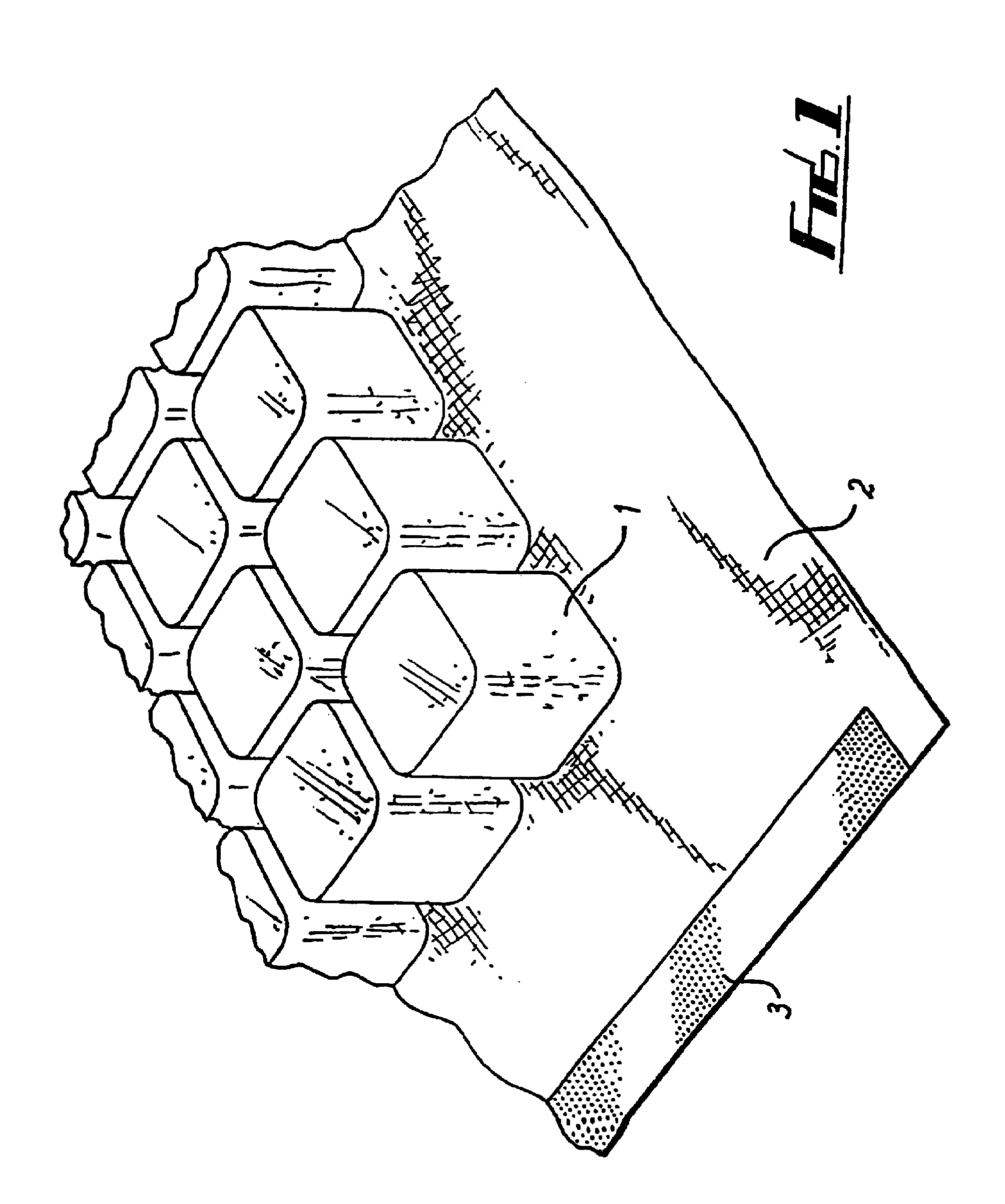
[0040]Referring to FIG. 1, a flexible material comprises a plurality of cubes 1 of a resilient closed-cell polyethylene foam, of side approximately 12 mm and with corners of radius approximately 2.5 mm, joined with a hot melt adhesive to a fabric substrate 2. The cubes 1 are evenly arranged, each cube being spaced from adjacent cubes by approximately 2 mm. The fabric 2 is a resiliently stretchable knitted fabric, preferably one comprising polyester or elastane fibers.

[0041]A margin of fabric 2 is provided around the periphery of the cubes 1. Along the edges of the fabric at opposite ends respectively there are strips 3 of VELCRO(™), only one of which is shown.

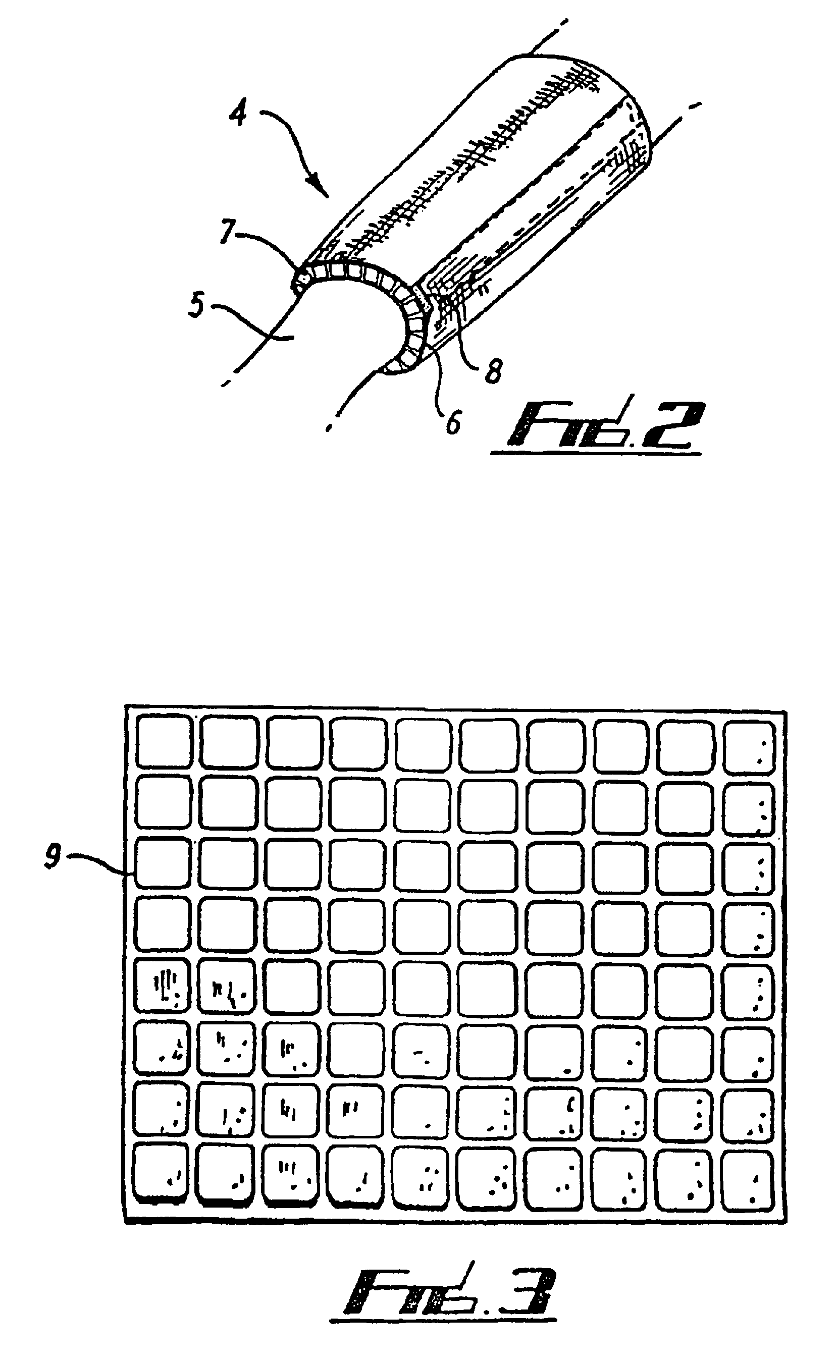
[0042]Referring to FIG. 2, a protective armband 4 is shown being worn on part of an arm 5. The armband 4 is formed from a generally rectangular piece of material of the type shown in FIG. 1 but which in this case comprises a fabric substrate 6 bonded to both sides thereof with a plurality of foam cubes 7 sandwiched therebetween...


PUM

PropertyMeasurementUnit
radiusaaaaaaaaaa
radiusaaaaaaaaaa
sizesaaaaaaaaaa

Abstract

A flexible material includes a plurality of separate resilient elements joined to a flexible, resiliently stretchable substrate. Such a material is suitable for providing protective war for human and animal bodies. Preferably, the elements includes a foam material such as a closed cell polyethylene foam and the substrate includes a knitted fabric. In an advantageous embodiment, a second flexible substrate is bonded over the elements to sandwich them between the two layers of substrate.

Description

RELATED U.S. APPLICATIONS[0001]Not applicable.[0002]Notice: multiple reissue applications have been filed for the reissue of U.S. Pat. No. 6,743,325. This application is a continuation reissue application of reissue application Ser. No. 12 / 642,522, filed on Dec. 18, 2009, which is a continuation reissue application of Ser. No. 11 / 269,919, filed on Nov. 8, 2005, now U.S. Pat. No. Re. 41,346, which is a reissue application of U.S. Pat. No. 6,743,325, filed as application Ser. No. 10 / 030,782 on Apr. 23, 2002, which claims priority to PCT / GB00 / 02687 filed Jul. 13, 2000; GB99 / 16291 filed Jul. 13, 1999; and GB 99 / 21804 filed Sep. 16, 1999; all of which are hereby fully incorporated by reference as if fully set forth herein.STATEMENT REGARDING FEDERALLY SPONSORED RESEARCH OR DEVELOPMENT[0003]Not applicable.REFERENCE TO MICROFICHE APPENDIX[0004]Not applicable.FIELD OF THE INVENTION[0005]The present invention relates to a method of manufacturing a flexible material suitable, primarily, for u...

Claims


Application Information

Patent Timeline
Patent Type & Authority Patents(United States)
IPC IPC(8): B32B38/04A41D13/05A41D31/00A47C31/12A61G7/057B32B3/16B63C9/093
CPCA41D13/05A61G7/05707B32B3/16B63C9/093A41D31/285Y10T156/13Y10T156/1077Y10T156/1754Y10T428/24355Y10T156/1067Y10T156/1087Y10T156/1093Y10T156/1095Y10T156/1092Y10T428/249953B32B2571/02B32B2266/08B32B2437/00B32B2266/025B32B5/18B32B3/18B32B5/026B32B5/245B32B7/12A41D13/0156
Inventor TAYLOR, DAVID STIRLING
Owner STIRLING MOLDINGS 2016 LTD
Learn More