
Method to improve cancerous lesion detection sensitivity in a dedicated dual-head scintimammography system

a dual-head scintimammography and sensitivity technology, applied in the field of dual-head scintimammography, can solve the problems of poor imaging sensitivity of lesions located in the medial aspect of the breast, poor performance, poor spatial resolution during imaging, etc., and achieve the effect of improving the contrast between background and lesion areas

Active Publication Date: 2012-07-03
JEFFERSON SCI ASSOCS LLC
View PDF7 Cites 1 Cited by
  • Summary
  • Abstract
  • Description
  • Claims
  • Application Information

AI Technical Summary

Benefits of technology

This method significantly improves the visibility of small lesions by increasing contrast and reducing background interference, allowing for more accurate detection and localization of potentially cancerous lesions regardless of their position within the breast.

Problems solved by technology

Currently scintimammography imaging to detect breast cancer is performed with standard nuclear medicine cameras and it suffers from poor sensitivity for lesions under about 1 cm in diameter and lesions located in the medial aspect of the breast, away from the large camera surface.
The main contributing factor to this poor performance is the poor spatial resolution during imaging due to the relatively large distance between the lesion and the collimator of the detector head.
While this improved approach confirmed that the dual head system is especially useful in most clinical situations where lesion location is not known a priori, the remaining important issue was how to combine most efficiently the two images obtained from the double sided imaging.
This technique further enhanced lesion vs. background contrast, but still did not produced the degree of contrast desired.

Method used


Image

  • Method to improve cancerous lesion detection sensitivity in a dedicated dual-head scintimammography system
  • Method to improve cancerous lesion detection sensitivity in a dedicated dual-head scintimammography system

Examples


Embodiment Construction

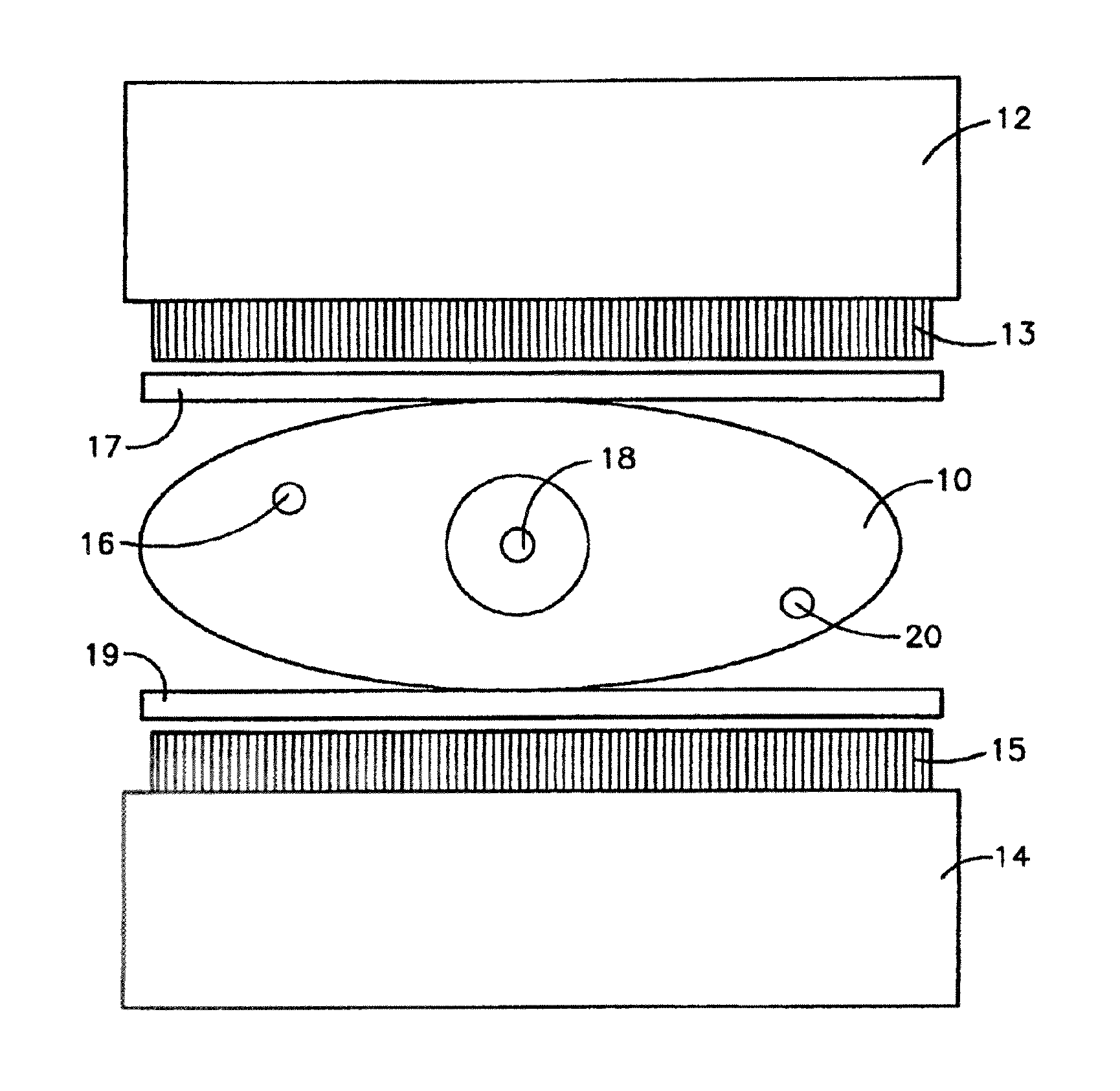
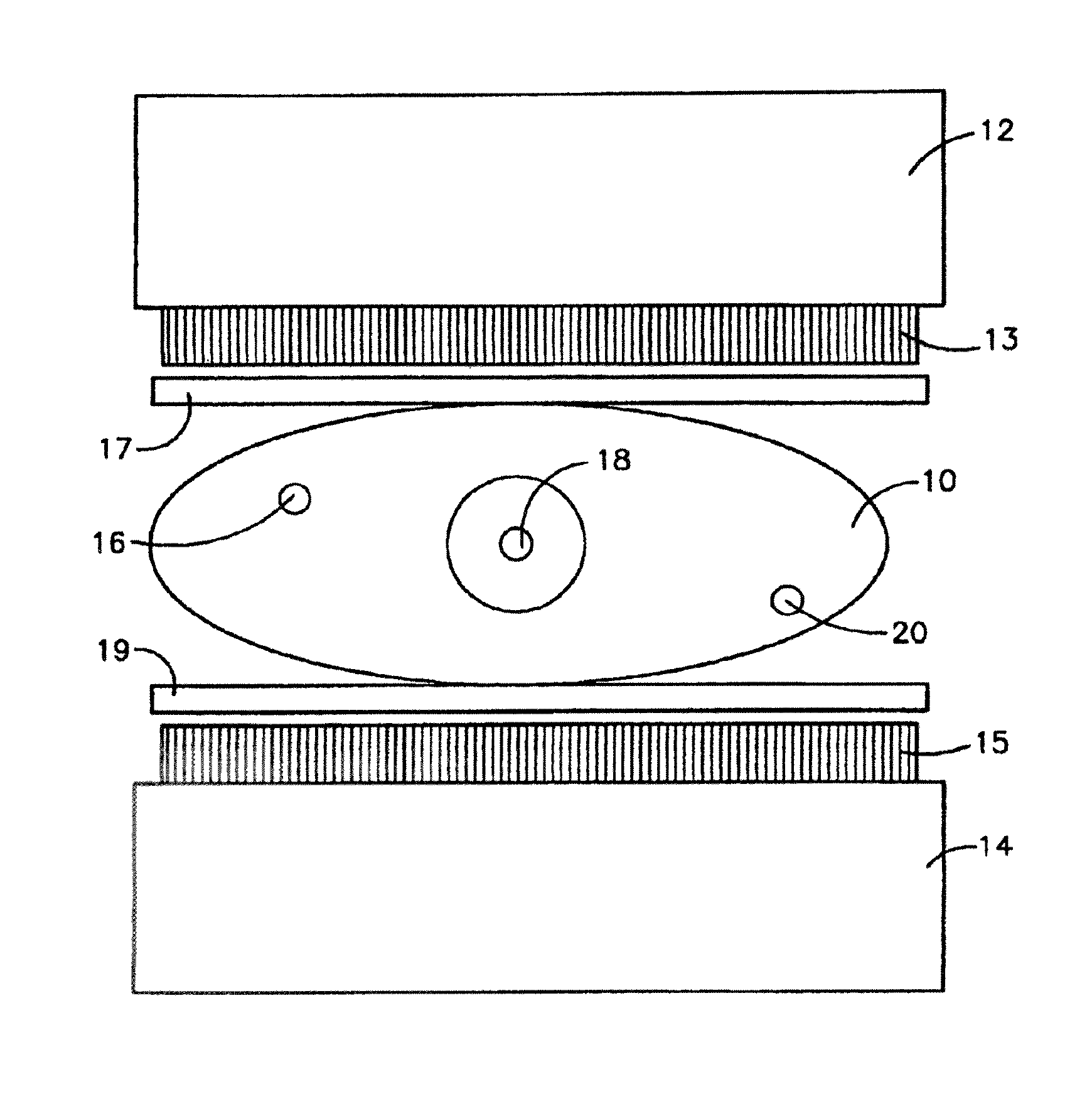
[0011]So called mini gamma or small field of view (FOV) cameras and their methods for use are well known in the art (see for example U.S. Pat. No. 6,271,525 to Majewski et al. whose description is incorporated herein by reference in its entirety) and commercially available from at least two sources: Dilon Technologies, 12050 Jefferson Ave., New Port News, Va. 23606; and Gamma Medica™, Inc., 19355 Business Center Drive, Suite 8, Northridge, Calif. 91324. Such cameras have been routinely applied to the examination of breasts for the presence of lesions by a process that involves injection of the patient with a radiopharmaceutical and examination of the breast with the mini gamma camera to detect differences in the uptake of the radiopharmaceutical between normal tissue and areas containing lesions.

[0012]In the 2002 paper by Kieper et al. described above, it was proposed to enhance lesion detection and localization through the use of a pair of opposed mini gamma cameras compressing the...


PUM


Abstract

An improved method for enhancing the contrast between background and lesion areas of a breast undergoing dual-head scintimammographic examination comprising: 1) acquiring a pair of digital images from a pair of small FOV or mini gamma cameras compressing the breast under examination from opposing sides; 2) inverting one of the pair of images to align or co-register with the other of the images to obtain co-registered pixel values; 3) normalizing the pair of images pixel-by-pixel by dividing pixel values from each of the two acquired images and the co-registered image by the average count per pixel in the entire breast area of the corresponding detector; and 4) multiplying the number of counts in each pixel by the value obtained in step 3 to produce a normalization enhanced two dimensional contrast map. This enhanced (increased contrast) contrast map enhances the visibility of minor local increases (uptakes) of activity over the background and therefore improves lesion detection sensitivity, especially of small lesions.

Description

[0001]The United States of America may have certain rights to this invention under Management and Operating Contract No. DE-AC05-84ER 40150 from the Department of Energy.FIELD OF THE INVENTION[0002]The present invention relates to dual-head scintimammography techniques for the detection and localization of cancerous lesions particularly in breast examinations and more particularly to a method for combining the information provided by the opposing heads in a dual head system to maximize system sensitivity for cancerous lesions.BACKGROUND OF THE INVENTION[0003]Currently scintimammography imaging to detect breast cancer is performed with standard nuclear medicine cameras and it suffers from poor sensitivity for lesions under about 1 cm in diameter and lesions located in the medial aspect of the breast, away from the large camera surface. The main contributing factor to this poor performance is the poor spatial resolution during imaging due to the relatively large distance between the l...

Claims


Application Information

Patent Timeline
Patent Type & Authority Patents(United States)
IPC IPC(8): G06K9/00A61B6/04
CPCA61B5/06A61B6/4258G01T1/1642G01T1/1644A61B6/502A61B6/583
Inventor KIEPER, DOUGLAS ARTHURMAJEWSKI, STANISLAWWELCH, BENJAMIN L.
Owner JEFFERSON SCI ASSOCS LLC
Learn More