Apparatus for directional boring under mixed conditions

a technology of mixed conditions and apparatus, applied in the direction of directional drilling, borehole/well accessories, surveying, etc., can solve the problem that the pushing force of the drill string alone is insufficient to steer the tool in soft ground without rotation, and achieve the effect of better steering

Inactive Publication Date: 2013-08-13
VERMEER MFG CO
View PDF95 Cites 8 Cited by
  • Summary
  • Abstract
  • Description
  • Claims
  • Application Information

AI Technical Summary

Benefits of technology

[0011]According to a further aspect of the invention, a method is provided for directional boring in mixed conditions including both soil and solid rock. Such a method comprises the steps of boring straight in both soil and rock by pushing and rotating the drill head with the drill string while delivering impacts to the bit with the hammer, prior to changing the boring direction in both soil and rock, determining the angular orientation of the gage tower using the device for detecting angular orientation, changing direction when boring in rock by pushing and rotating the bit repeatedly over an angle defined by less than a full rotation of the bit while delivering impacts to the bit with the hammer, so that the drill head deviates in the direction of the cutting action of the gage tower, and changing direction when boring in soil by pushing the bit with the drill string without rotating it so that the drill head deviates in a direction of the gage tower and away from the heel portion. Since the main cutting face of the drill bit is large and flat, the pushing force of the drill string alone may be insufficient to steer the tool in soft ground without rotation. It is thus preferred to deliver impacts to the bit with the hammer while changing direction in soil. This method of the invention may provide better steering in some ground conditions.

Problems solved by technology

Since the main cutting face of the drill bit is large and flat, the pushing force of the drill string alone may be insufficient to steer the tool in soft ground without rotation.

Method used


Image

  • Apparatus for directional boring under mixed conditions
  • Apparatus for directional boring under mixed conditions
  • Apparatus for directional boring under mixed conditions

Examples


Embodiment Construction

[0057]While making and using of various embodiments of the present invention are discussed in detail below, it should be appreciated that the present invention provides many applicable inventive concepts which can be embodied in a wide variety of specific contexts. The specific embodiments discussed herein are merely illustrative of specific ways to make and use the invention and are not to delimit the scope of the invention. References to a numbered element shown in several alternative forms designated A, B etc. without such a letter are intended to refer to all of the alternative forms.

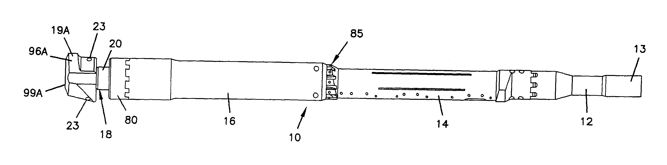
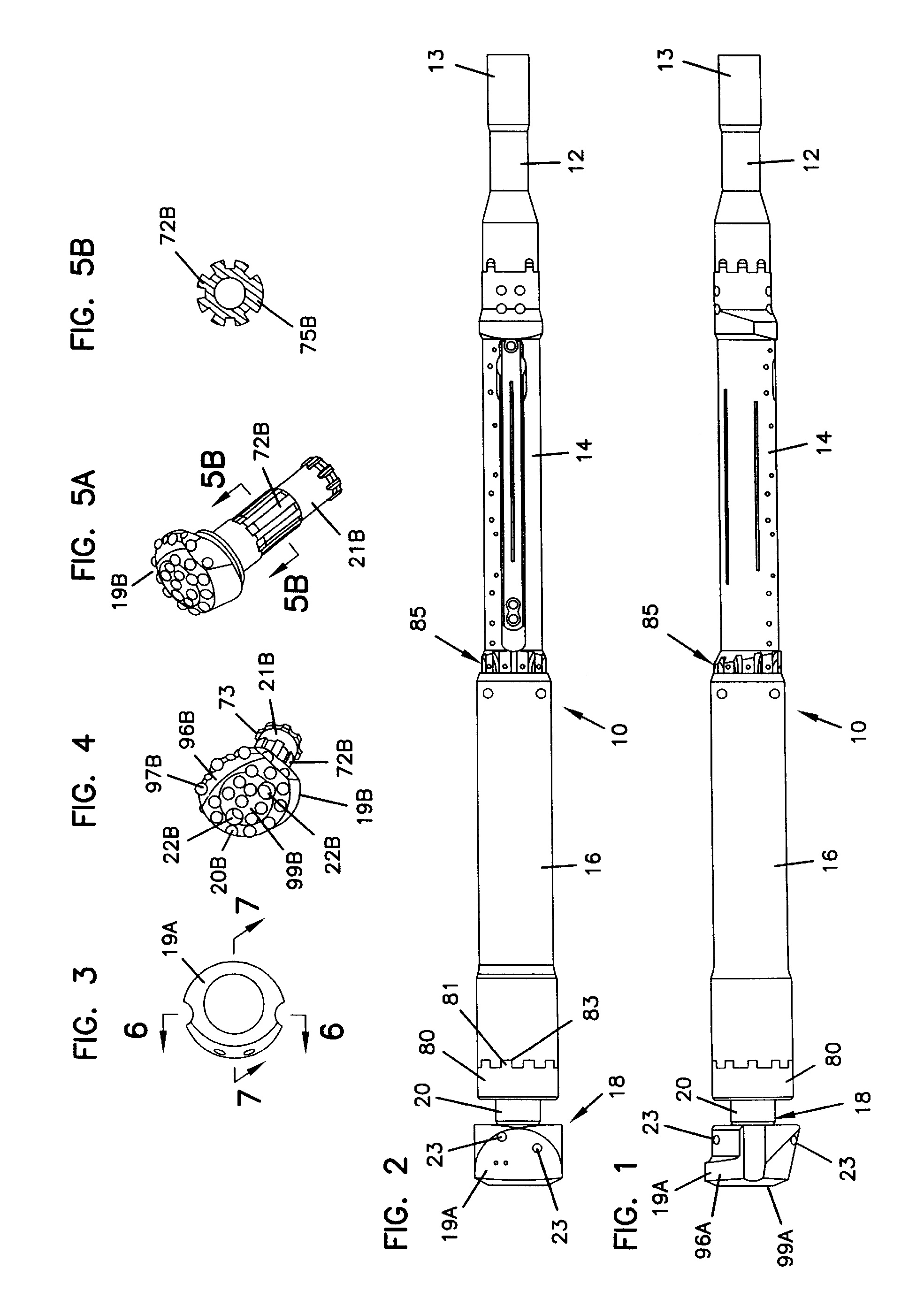
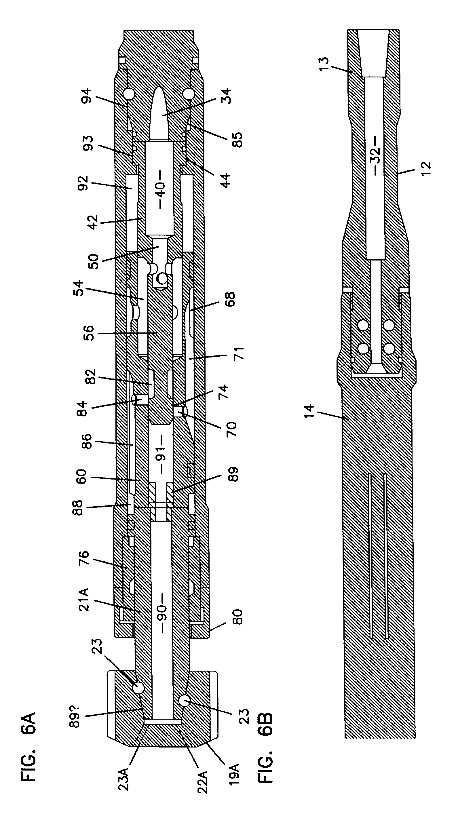
[0058]Referring to FIGS. 1-3, 6A-6B and 7A-B, a drill head 10 according to the invention includes, as general components, a sonde holder 14, pneumatic hammer 16 and bit assembly 18 connected head to tail as shown. As noted above, the drill head 10 can also include a starter rod 12. Starter rod 12 connects at its rear end 13 to a conventional drill string driven by a directional boring machine, and c...


PUM


Abstract

A drill head for an apparatus for horizontal directional drilling. The drill head includes a device for detecting angular orientation, a holder for the device for detecting angular orientation, the device for detecting angular orientation being disposed therein, a hammer driven by a liquid and a drill bit. The holder, the hammer and the drill bit are connected head to tail along a longitudinal axis of a drill string with the holder at a proximate end of the drill head and the drill bit at a distal end of the drill head.

Description

[0001]This application claims the benefit of U.S. Provisional Application No. 60 / 122,593, filed Mar. 3, 1999.TECHNICAL FIELD OF THE INVENTION[0002]The invention relates to directional boring and, in particular to a system for boring through both soil and solid rock using the same machine.BACKGROUND OF THE INVENTION[0003]At present, when underground utilities such as natural gas, potable water, or sanitary sewer pipes are placed in rock, trenches are excavated using large hard rock trenching equipment such as the Vermeer T-655, or possibly even shot using explosives. In these conditions, electric, telephone and cable TV lines are normally strung overhead along poles, mostly due to the difficulty and expense of placing them underground. Thus, in many situations, a solid rock formation will cause utility lines to be located above ground due to the difficulty of underground installation. Many such sites involve mixed conditions involving both a solid rock formation for part of the run a...

Claims


Application Information

Patent Timeline
Patent Type & Authority Patents(United States)
IPC IPC(8): E21B10/00E21B4/14E21B4/20E21B7/06E21B7/08E21B10/36E21B10/56E21B47/02
CPCE21B4/14E21B7/068E21B10/56E21B47/02E21B4/20E21B10/36
Inventor RUNQUIST, RANDY R.VAN HOUWELINGEN, MARKRANKIN, JAMES R.ALBERT, RENEMARCEL
Owner VERMEER MFG CO
Why Eureka
Try Eureka