Flexible material

a flexible material and manufacturing method technology, applied in the field of flexible material manufacturing, can solve the problems of restricting limiting the movement of wearers, and expensive or inconvenient supply of different sizes

Inactive Publication Date: 2015-03-03
STIRLING MOLDINGS 2016 LTD
View PDF125 Cites 4 Cited by
  • Summary
  • Abstract
  • Description
  • Claims
  • Application Information

AI Technical Summary

Benefits of technology

[0013]It is an object of the present invention to overcome, or at least reduce, the problems associated with the manufacture of conventional protective material and with protective wear made therefrom.

Problems solved by technology

There are, however, a number of problems with this arrangement.
Provision of different sizes can be expensive or inconvenient.
Also, closely fitting articles can restrict movement of the wearer, especially when worn on or near joints.
However, the foram elements of the bandage touch one another at their base, which restricts the stretchability of the material as a whole and is also designed to be worn with the elements in contact with the skin, which would restrict movement.
A moulded foam article can only correctly fit a joint when in one position.
When the joint moves, the article will no longer fit correctly.
This may reduce the protection it affords.
Such materials are time consuming to produce.
Also, such materials can generally only easily be flexed in a direction perpendicular to that of the strips of foam.
Flexing the material in a direction along the length of the strips involves flexing the strips themselves which, depending on the type of foam used, can be difficult.

Method used


Image

  • Flexible material
  • Flexible material
  • Flexible material

Examples


Embodiment Construction

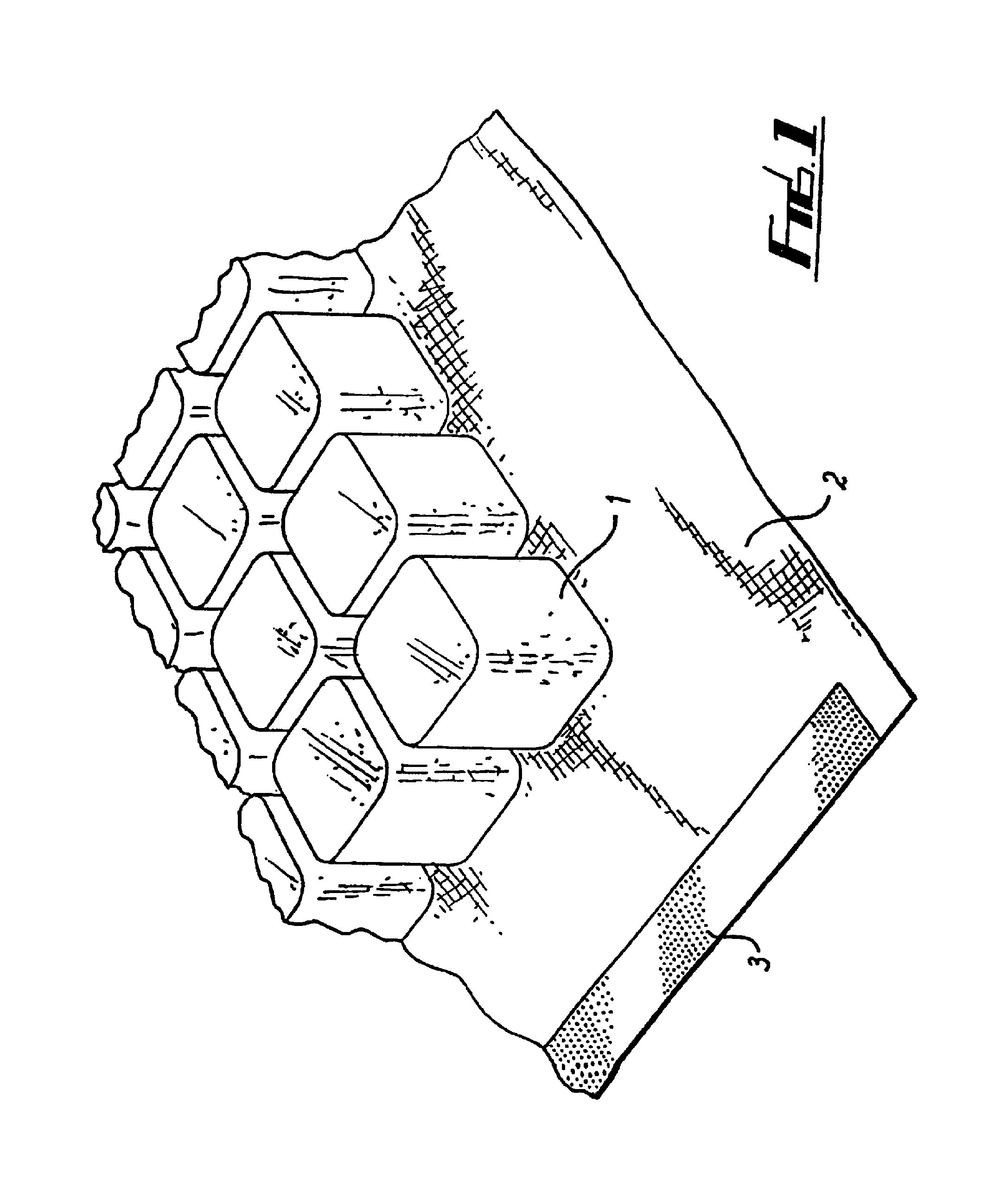
[0040]Referring to FIG. 1, a flexible material comprises a plurality of cubes 1 of a resilient closed-cell polyethylene foam, of side approximately 12 mm and with corners of radius approximately 2.5 mm, joined with a hot melt adhesive to a fabric substrate 2. The cubes 1 are evenly arranged, each cube being spaced from adjacent cubes by approximately 2 mm. The fabric 2 is a resiliently stretchable knitted fabric, preferably one comprising polyester or elastane fibers.

[0041]A margin of fabric 2 is provided around the periphery of the cubes 1. Along the edges of the fabric at opposite ends respectively there are strips 3 of VELCRO(™), only one of which is shown.

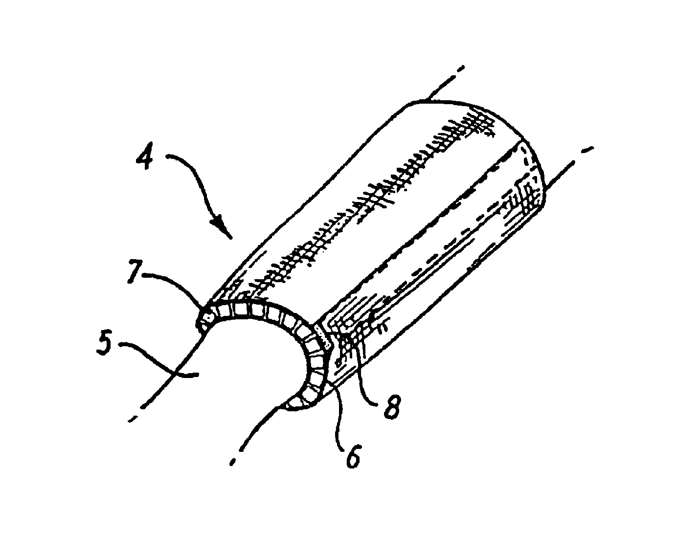
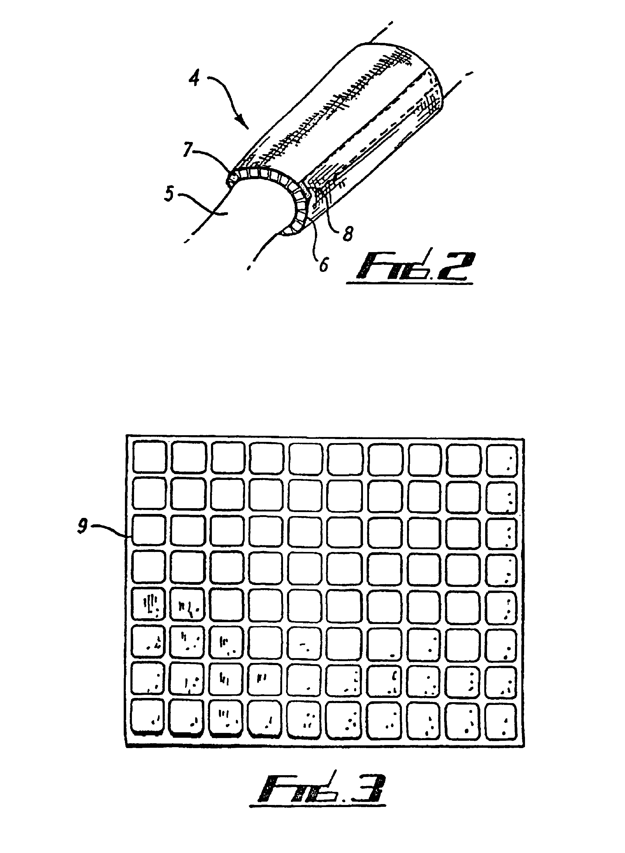
[0042]Referring to FIG. 2, a protective armband 4 is shown being worn on part of an arm 5. The armband 4 is formed from a generally rectangular piece of material of the type shown in FIG. 1 but which in this case comprises a fabric substrate 6 bonded to both sides thereof with a plurality of foam cubes 7 sandwiched therebetween...


PUM

PropertyMeasurementUnit
distanceaaaaaaaaaa
radiusaaaaaaaaaa
radiusaaaaaaaaaa

Abstract

A flexible material includes a plurality of separate resilient elements joined to a flexible, resiliently stretchable substrate. Such a material is suitable for providing protective war for human and animal bodies. Preferably, the elements includes a foam material such as a closed cell polyethylene foam and the substrate includes a knitted fabric. In an advantageous embodiment, a second flexible substrate is bonded over the elements to sandwich them between the two layers of substrate.

Description

[0001]Notice: multiple reissue applications have been filed for the reissue of U.S. Pat. No. 6,743,325. This application is a continuation reissue application of reissue application Ser. No. 12,642,550, Dec. 18, 2009, which is a continuation reissue application of reissue application Ser. No. 11 / 269,919 filed Nov. 8, 2005, now U.S. Pat. No. Re. 41,346, which is a reissue application of U.S. Pat. No. 6,743,325, filed as application Ser. No. 10 / 030,782 on Apr. 23, 2002, which claims priority to PCT / GB00 / 02687 filed Jul. 13, 2000; GB99 / 16291 filed Jul. 13, 1999; and GB 99 / 21804 filed Sep. 16, 1999; all of which are hereby fully incorporated by reference as if fully set forth herein. In addition to the above applications, the following also are all continuation reissue applications of reissue application Ser. No. 11 / 269,919, filed Nov. 8, 2005, now U.S. Pat. No. Re. 41,346: continuation reissue application Ser. No. 11 / 642,522 filed Dec. 18, 2009, now U.S. Pat. No. Re. 42,689; continuati...

Claims


Application Information

Patent Timeline
Patent Type & Authority Patents(United States)
IPC IPC(8): B32B38/04
CPCB32B38/04B32B37/12
Inventor TAYLOR, DAVID STIRLING
Owner STIRLING MOLDINGS 2016 LTD
Why Eureka
Try Eureka