Driver's cab structure for load-carrying vehicle

A technology for working vehicles and cabs, which is applied in the field of cab structures, can solve problems such as deformation, unsatisfactory strength, and impracticality, and achieve the effects of reducing cross-sectional area, improving visibility, and improving cross-sectional strength

Inactive Publication Date: 2007-08-29
KOMATSU LTD
View PDF7 Cites 0 Cited by
  • Summary
  • Abstract
  • Description
  • Claims
  • Application Information

AI Technical Summary

Problems solved by technology

However, in order to form such a shape, it is necessary to draw it through different drawing dies many times, which is expensive in processing, and it is not practical unless it can be mass-produced.
In addition, when this kind of plastic processing is carried out to make products, there is concern that the strength will not be ideal due to the selection of materials used.
In addition, although it is necessary to cut the formed material into a specified size for the parts used in the straight part, when it is further bent and used as a part of the frame, heating bending or cold drawing bending must be performed, so Deformation such as distortion may occur and cause problems in productization
Therefore, even if the feasibility of the use of the part is confirmed, there are many problems in constituting the frame of the cab by components having such a complicated cross-sectional structure.

Method used


Image

  • Driver's cab structure for load-carrying vehicle
  • Driver's cab structure for load-carrying vehicle
  • Driver's cab structure for load-carrying vehicle

Examples


Embodiment Construction

[0023] Hereinafter, specific examples of the cab structure of the work vehicle according to the present invention will be described with reference to the drawings.

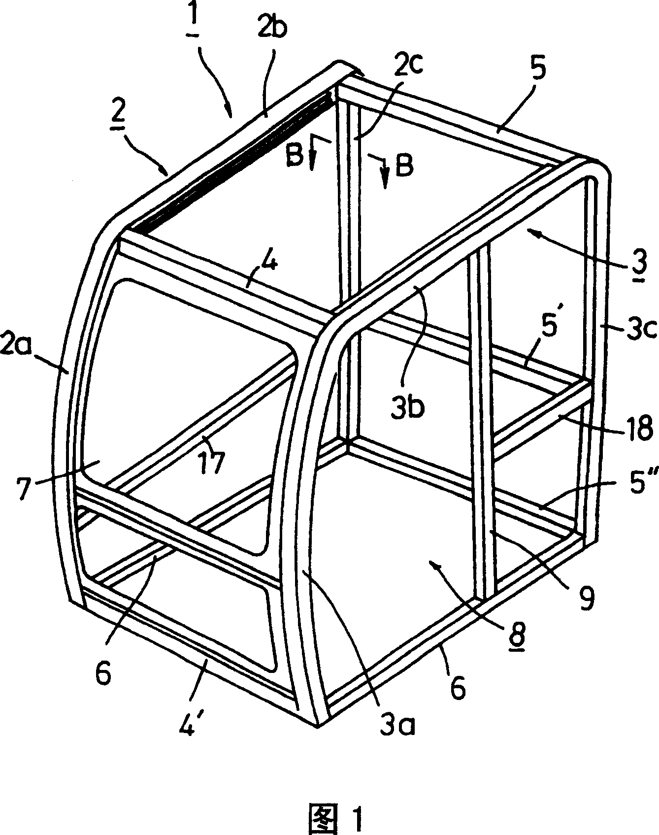
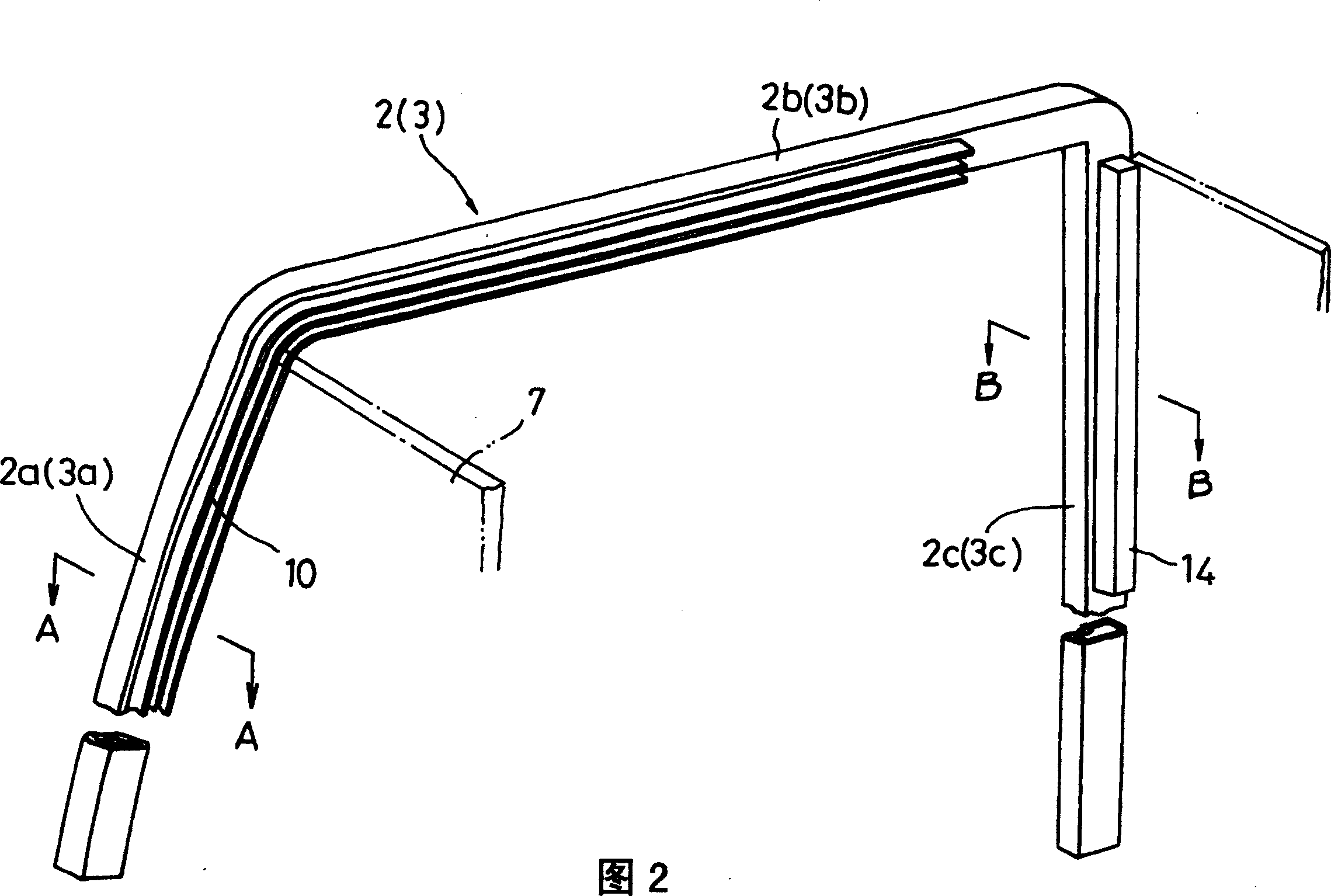
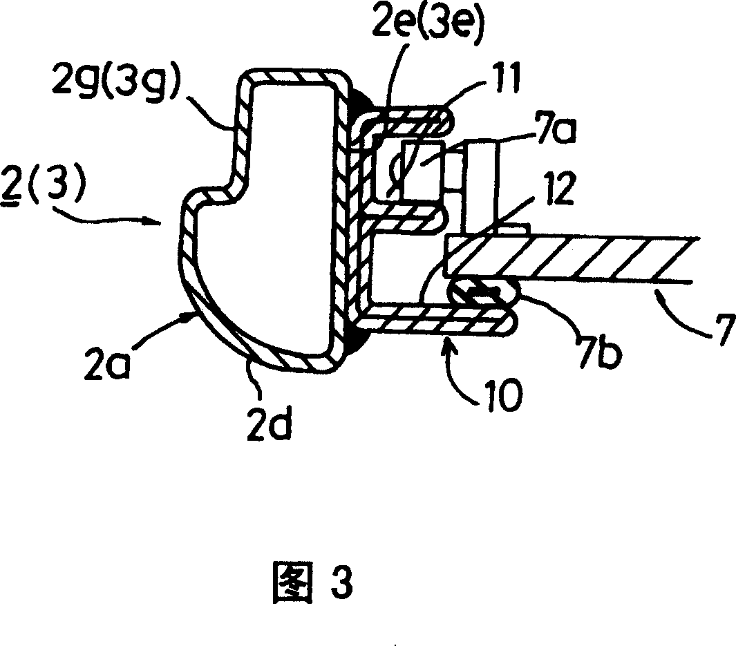
[0024] FIG. 1 is a perspective view showing a frame structure of a cab mounted on a work vehicle according to the present embodiment. Fig. 2 is a perspective view showing main frame forming members forming one side surface of a cab frame. Fig. 3 is an enlarged sectional view taken along line A-A of Fig. 2 . Fig. 4(a) is an enlarged cross-sectional view taken along the line B-B in Fig. 2, and Fig. 4(b) is an enlarged cross-sectional view of another example. 5( a ), ( b ) are enlarged planar sectional views showing the support in the middle portion.

[0025] The cab structure of this embodiment is applied to a hydraulic excavator as a construction machine.

[0026] In the cab of this embodiment, the frame 1 constituting it is assembled using pipe materials. On this frame 1, the side members 2, 3 on the left and ...


PUM


Abstract

A work vehicle cab structure is provided, which does not use members having a complicated sectional structure but uses a pipe member having a modified sectional structure and high workability, thereby achieving increased functionality as well as increased sectional strength for rational reinforcement. The main framework of a cab is constituted by a pipe member which has one flat face at least at a side face thereof and a member (side member) attached to the flat face, the side member having a sectional shape that provides functionality. The pipe member of the main framework constitutes a front supporting column, a ceiling longitudinal part and a rear supporting column which are integrally formed by bending, and the member (e.g., a guide rail and a pipe member for a window) having a sectional shape that provides functionality is welded to the flat face of the pipe member in a specified region, thereby forming an integral structure.

Description

technical field [0001] The invention relates to a cab structure of construction machines such as hydraulic excavators, agricultural machines such as tractors, and other industrial machinery operating vehicles. Background technique [0002] Work vehicles include construction machinery, agricultural machinery, and other loading and unloading machinery. Among them, hydraulic excavators among construction machinery are widely used in civil engineering, construction foundation engineering, or building demolition accompanied by excavation of soil and sand. During these works, the operator drives the working machine while looking ahead mainly through the front window from the cab. The cab of such a work vehicle that performs work while looking ahead from the cab does not have a spacious structure in terms of the structure of the vehicle on which the work machine is mounted, but it is desired to ensure a wide field of view during work. [0003] In addition, in working vehicles such...

Claims


Application Information

Patent Timeline
Patent Type & Authority Patents(China)
IPC IPC(8): B62D33/06E02F9/16B62D25/04B62D25/06
CPCB62D33/06B62D25/04B62D25/06B60J1/04E02F9/16
Inventor 伊藤达志
Owner KOMATSU LTD
Why Eureka
Try Eureka