
Float valve fixing column plate

A floating valve tray and valve plate technology, applied in fractionation and other directions, can solve the problems of weakening, weakening the mass transfer function of the tray, reducing the efficiency of the tray, etc., and achieving the effect of reducing resistance, reducing resistance and improving flux

Inactive Publication Date: 2007-09-05
NANJING UNIV
View PDF0 Cites 0 Cited by
  • Summary
  • Abstract
  • Description
  • Claims
  • Application Information

AI Technical Summary

Problems solved by technology

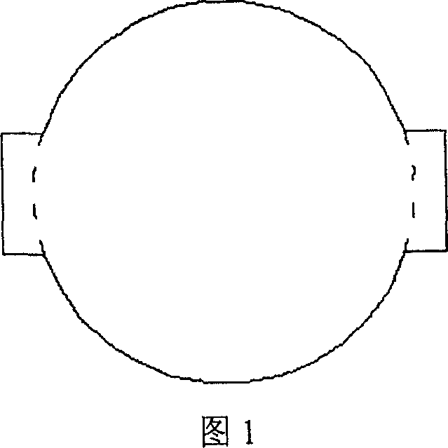
For the round valve, the gas outlet is a circular arc, so the gas ejected from the first half of the outlet has a certain liquid pushing effect, but because the gas ejected from the second half of the outlet of the front solid valve has a liquid blocking effect, the two kinds of action parts counteract each other
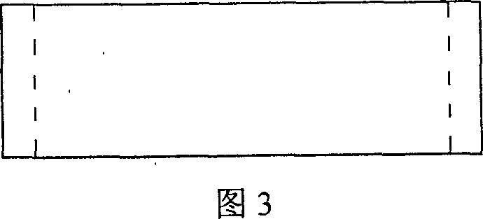
For the strip-shaped solid valve, the gas phase outlet is a straight line, and the direction of the gas ejection is perpendicular to the direction of the liquid flow. Not only does it not have the effect of pushing the liquid, but also because the directions of the gas ejected from two adjacent valve plates are relatively close and the distance is very close. Cause serious spray phenomenon, easy to generate a large amount of mist entrainment, weaken the mass transfer function of the tray, and reduce the efficiency of the tray

Method used


Image

  • Float valve fixing column plate
  • Float valve fixing column plate
  • Float valve fixing column plate

Examples


Embodiment 1

[0019] Propylene oxide (PO)-water rectification system adopts the fixed valve tray of the present invention to transform the original F1 type valve tray, the tower diameter is Φ1200mm, the number of trays is 50, the plate spacing is 450mm, and the material is stainless steel. Use the fixed floating valve tray of the present invention instead, as shown in Figure 5 and Figure 6, the long side length a=50mm of the valve plate; the width b=25mm of the valve plate; the width c=8mm of the valve leg; the total length of the valve plate The length d=70mm; the height of the solid valve h=4mm; the length of the valve hole is l=75mm. As shown in Figure 7, the fork row method is adopted, the valve center distance s=70mm, the distance between rows t=60mm, and the processing capacity is F=18000t / a=2500kg / h (calculated on the basis of 300 days a year). The operation results show that the processing capacity of this tray is 15% higher than that of the F1 float valve, the purity of PO after se...

Embodiment 2

[0021] The ethanol-water rectification system was originally an ordinary sieve tray. The equipment has been abnormal since it was put into operation. The main performance is that the production load is low, which can only reach 90% of the original design load, and the product is unqualified if the working conditions and load fluctuate slightly. After many observations, adjustments, and repeated calculations It is considered that the efficiency of the tray is reduced because the gas perforation velocity is too high. In order to improve the condition of this set of equipment, the fixed valve tray of the present invention is adopted. The original rectification tower is Φ1600mm, with 55 trays, and the opening ratio is 12%. All trays are changed into fixed valve trays of the present invention. As shown in Figure 5 and Figure 6, the length of the long side of the guide valve plate is a=40mm; the width of the valve plate is b=20mm; the width of the valve leg is c=6mm; the length of...


PUM


Abstract

A fixed float valve plate, comprising orifice valve and valve block, the valve block is a quadrangle similar to diamond with macro-diagonal line as bilateral symmetry, the separation angle of the long line points to the overflow dam, the length of the valve block long line a is 10-80 mm, the width of the valve block b is 8-60 mm, the width of the valve leg c is 4-20 mm, the length of the valve block d is 15-90 mm, the height of the valve leg h is 3-8 mm, the length of the valve pore I is 15-100 mm, the valve leg connects the valve block with the valve plate. The fixed float valve plate in this invention can push the liquid to the overflow dam to decrease the liquid level drop height, and eliminate the convolution and back-mix-flow effectively, thus increase the valve plate efficiency. The side edge of broken line similar to diamond is longer than that of rectangular straight line and circular arcuate path, which makes the outlet of air passage be larger, and increase the pass amount effectively and the contacting area of the gas-liquid mass transfer, which can not only increase the transferring efficiency but the pore speed of the gas decreases under the same treating amount, thus decreasing the valve plate resistance force.

Description

technical field [0001] The invention relates to the core component of the fixed valve tower - the fixed valve tray. Background technique [0002] Solid valve tray has the advantages of large production capacity, high tray efficiency, low processing and maintenance costs, and is very popular in the industry. At present, the fixed valves of the valve-fixed trays in the industry are mainly circular fixed valves (see Figures 1 and 2) and strip-shaped fixed valves (Figures 3 and 4). These two kinds of fixed float valves mainly have the following characteristics: directly punch out circular and strip-shaped protrusions on the plane of the tray, use the edge opening as a gas phase channel, and have a valve leg at the front and back of the valve plate to connect with the tray. It plays the role of supporting the valve plate, and the angle between the valve leg and the plane of the tray is about 100 degrees. On the same tray, the circular fixed float valves or bar-shaped fixed floa...

Claims


Application Information

Patent Timeline
Patent Type & Authority Patents(China)
IPC IPC(8): B01D3/18
Inventor 周政张志炳梁银春耿皎孟为民
Owner NANJING UNIV
Learn More