Mini jockey pump

A thin-film pump and miniature technology, applied in the direction of pumps, pump control, pumps with flexible working elements, etc., can solve the problems of self-starting, complex structure, high production cost, etc., achieve reduced volume, reliable operation, and simple production Effect

Inactive Publication Date: 2007-09-05
TSINGHUA UNIV
View PDF4 Cites 1 Cited by
  • Summary
  • Abstract
  • Description
  • Claims
  • Application Information

AI Technical Summary

Problems solved by technology

At present, the general micropump structure is more complicated, the production cost is higher, and it cannot realize self-starting.

Method used


Image

  • Mini jockey pump
  • Mini jockey pump
  • Mini jockey pump

Examples


Embodiment 1

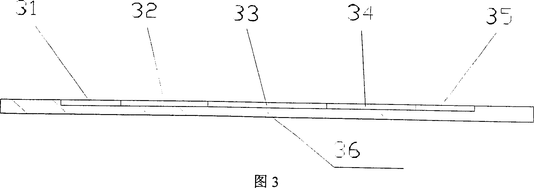
[0019] The structure of the pump body of Embodiment 1 is shown in Figure 4, wherein, the middle of the pump body is a circular pump cavity with a diameter of 4-8 mm, and both sides are circular liquid inlets 31 and liquid outlets 35, both of which have a diameter of 1 -3 mm, between the pump cavity and the liquid inlet and outlet, there are miniature cone valves 32 and microvalve 34 with the same direction, the small ports are 0.05-0.2 mm, the taper is 3-10 degrees, and the length is 2-4 mm.

[0020] The film material is polydimethylsiloxane (Polydimethylsiloxane, PDMS), the thickness of the film is 0.1-1 mm, and the height of the pump cavity 33 is 10-100 microns.

Embodiment 2

[0021] The structure of the pump body of Embodiment 2 is shown in Figure 5. The difference between this embodiment and the first embodiment is that the miniature taper valve between the pump chamber and the liquid inlet and outlet can be two taper pipes arranged side by side 52, 54 , It can also be used in parallel for multiple tapered tube valves, which can increase the flow rate.

Embodiment 3

[0022] The structure of the pump body of Embodiment 3 is shown in Figure 6. The difference between this embodiment and the first embodiment is that the micro-valve integrated on the film can be a circle with many pairs of wedges 66 arranged in a staggered manner on its inner wall. The number of wedge valves 62, 64 formed by tubes and wedges 66 can be 1 row of 4, 2 rows of 4, 3 rows of 6, 4 rows of 8, etc.


PUM


Abstract

The invention belongs to micro flow pump technology field in precision machinery, which refers to micro film pump, which is made up of an upper and a subjacent bracket, a piece of cover, a film and a double-swage beam; the two brackets are integrated together, the cover piece, film and cushion are pressed and overlapped between the two brackets; there has a ventilation hole in the middle part of the upper bracket to make the piece extrude out, the cover piece has two ventilation holes acted on liquid inlet and outlet; the middle part of the film forms liquid storing, and flow area, the area includes liquid inlet, the first micro valve, pump cavity, the second micro valve whose direction is the same to the first micro valve direction, liquid outlet, the bottom of the area is pump film, the cover combines with the film and forms the pump. The structure of the invention is simple, it is reliable.

Description

technical field [0001] The invention belongs to the technical field of micro-fluid pumps in precision machinery, and in particular relates to the structural design and manufacturing method of micro-film pumps. Background technique [0002] In recent years, with the development of biochemical analysis and medical technology such as biochips and micro-dosing, the requirements for micro-liquid delivery have become more prominent. At the same time, micro-energy systems, precision biological experiment research, and fine chemical industry also require the supply of trace liquids that can be precisely controlled. At present, the general micropump has a complicated structure, high manufacturing cost, and cannot realize self-starting. Contents of the invention [0003] The purpose of the present invention is to provide a micro-membrane pump driven by a double piezoelectric beam to meet the needs of the application, which has the advantages of simple structure, reliable operation,...

Claims


Application Information

Patent Timeline
IPC IPC(8): F04B43/04F04B49/06A61M5/14
Inventor 叶雄英朱亮周兆英
Owner TSINGHUA UNIV
Why Eureka
Try Eureka