Flow restrictor

A flow restriction, restrictor technology, used in chemical instruments and methods, mechanical equipment, dissolution, etc., to solve problems such as easy damage to components, incorrect reinstallation, operator exposure, etc.

Inactive Publication Date: 2007-09-05
JOHNSONDIVERSEY INC
View PDF9 Cites 0 Cited by
  • Summary
  • Abstract
  • Description
  • Claims
  • Application Information

AI Technical Summary

Problems solved by technology

This method of flow regulation has several disadvantages, mainly due to the fact that it is difficult to vary the flow of the liquid to be diluted in the injector
This is because it is difficult to remove and replace elements with flow restriction channels with flow restriction elements suitable for different flow rates
This involves, in part, dismantling the * injector, which is an arduous task and can result in leakage of the diluted solution, possibly even exposing the operator to a potentially hazardous solution
[0005] Therefore, components that are removed in order to change the flow rate may be easily damaged and may be incorrectly reinstalled in the injector, which in turn causes other problems

Method used


Image

  • Flow restrictor
  • Flow restrictor
  • Flow restrictor

Examples


Embodiment Construction

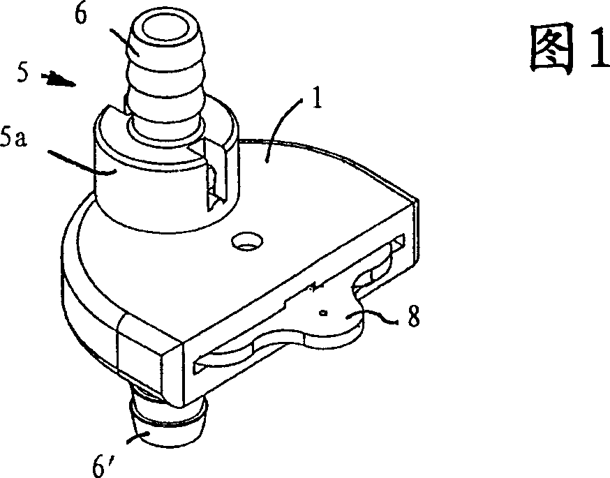
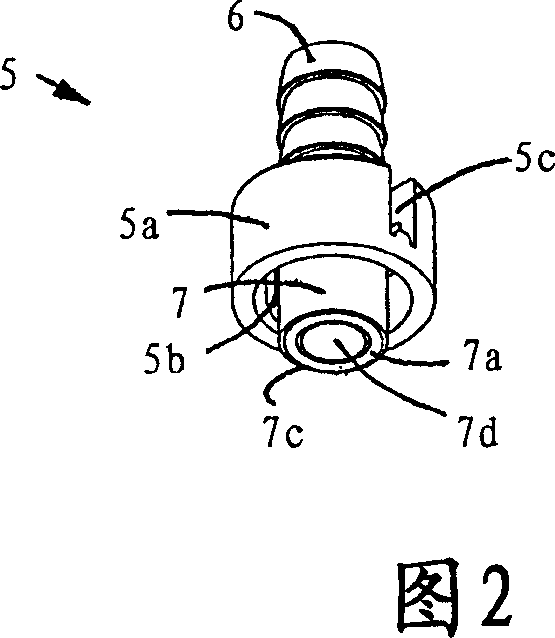
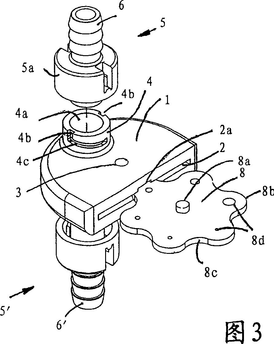
[0021] Figures 1 to 3 show a liquid flow restrictor embodying the present invention in the form of a housing 1 in which the orifices 4a of the housing connector 4 are located on both sides of the housing (only one is visible). The respective ends 7 of the one-to-one identical flow conduits 5, 5' pass through the orifice 4a when the housing 1 and the flow conduit 5 are assembled. Each flow conduit 5, 5' has a central axial tube providing a flow path 7b and an integral fitting 6, 6' for connecting a flow restrictor in the supply line of a device such as an injector provided. Around the central tube is an integrally formed sleeve portion 5a. The axes of the two orifices 4a are aligned with each other, and the orifices 4a extend from outside the casing 1, through the casing wall, to the cavity 2 inside the casing 1.

[0022] The cavity 2 of the housing has a substantially flat shape and an orifice leading to one side of the housing, as can be seen in FIGS. 1 and 2 . The cavity 2...


PUM


Abstract

A liquid flow restrictor in the supply line of an eductor or other dilution or dispensing device has a rotatably mounted disc (8) with opposite faces and a plurality of apertures or holes (8d), which provide different flow restrictions between the faces, and a pair of flow conduits (5, 5') sealingly engaging against the faces, whereby on rotation of the member (8) the zones are selectively brought into communication with the conduits (5, 5') to provide a desired flow restriction.

Description

technical field [0001] This invention relates to the field of liquid flow regulation, eg in the supply line of chemical dilution devices such as eductors. Background technique [0002] Chemicals such as those used for cleaning are purchased as concentrated liquids and then diluted with water in order to obtain the correct concentration for use, a common practice in many industries such as hotels and restaurants. To achieve the intended dilution of concentrated solutions and to dispense mixed diluted solutions, proportional dispensing devices have been designed. [0003] These dispensers typically use a venturi type device known as an ejector to draw the concentrated solution into the water stream, see eg WO 94 / 04857. In these eductors, the water flowing through the pipe carries away the concentrated solution at the point in the pipe where the restricted flow channel widens. [0004] In order to ensure that the solution is dispensed at the desired concentration, a method of...

Claims


Application Information

Patent Timeline
Patent Type & Authority Patents(China)
IPC IPC(8): F16L55/10F16K3/08E03C1/08F16L55/00B01F15/02F16K3/32
CPCF16K3/085F16L55/10F16K3/08E03C1/08
Inventor 斯蒂芬·奥利弗
Owner JOHNSONDIVERSEY INC
Why Eureka
Try Eureka