End socket forming die and end socket forming method

A technology for forming molds and heads, which is used in household appliances, other household appliances, applications, etc., can solve the problems of uneven thickness of the head and high raw material cost, so as to slow down the local excessive stretching and thinning, and reduce the cost of raw materials. , The effect of uniform thickness of the head

Pending Publication Date: 2021-02-02
CIMC SAFEWAY TECH CO LTD
View PDF0 Cites 0 Cited by
  • Summary
  • Abstract
  • Description
  • Claims
  • Application Information

AI Technical Summary

Problems solved by technology

[0005] In order to solve the problems of relatively uneven thickness and high cost of raw materials in the prior art, the invention provides a head forming mold and a method for forming a head

Method used


Image

  • End socket forming die and end socket forming method
  • End socket forming die and end socket forming method
  • End socket forming die and end socket forming method

Examples


Embodiment 1

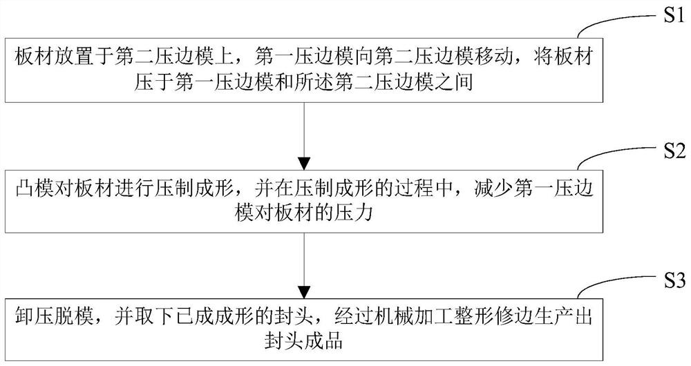
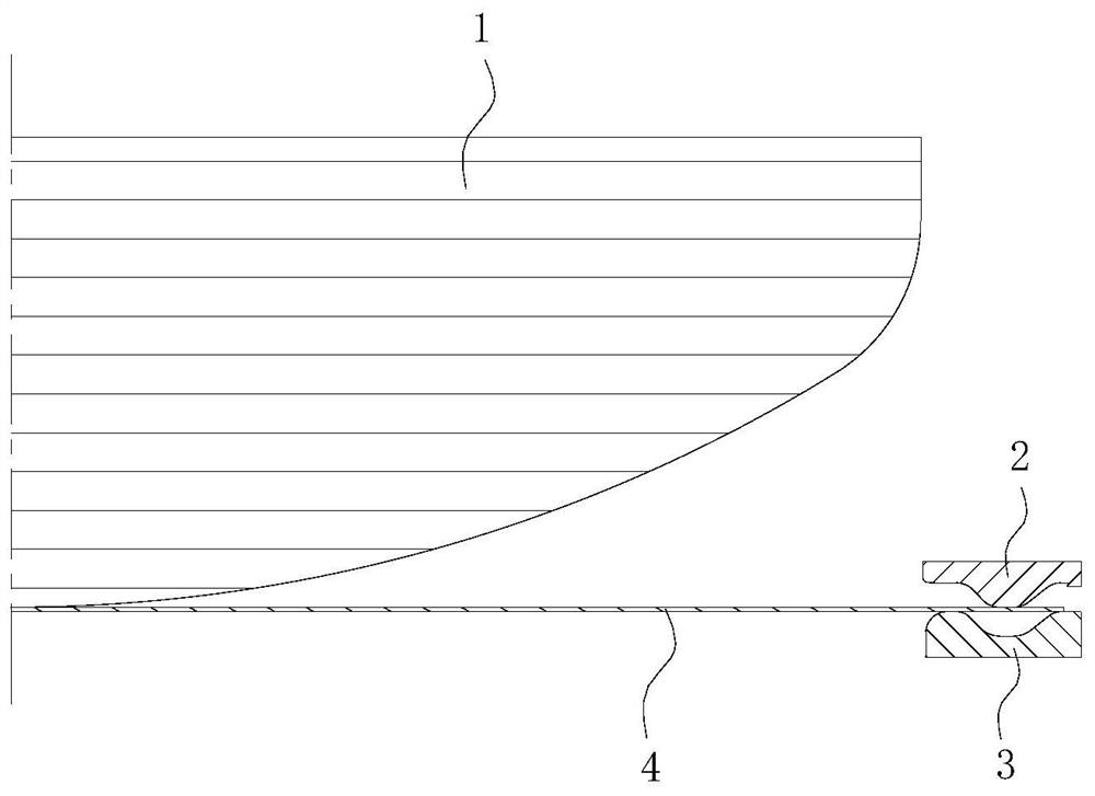
[0061] The diameter of the head product is required to be 2000 mm, the initial pressure of the first blank holder 2 on the plate 4 is 28000 kN, and the four stroke sections of the punch 1 are divided as follows:

[0062] The first stroke section is to continue to move from 0 mm to 100 mm after the punch 1 contacts the plate 4, the second stroke section is to move from the punch 1 to 100 mm to 310 mm, and the third stroke section is to move from the punch 1 to 310 mm to 380 mm, the fourth stroke section is to move from punch 1 to 380 mm to 470 mm.

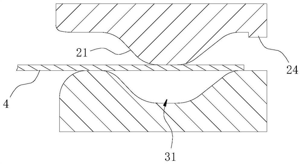
[0063] Before the start of each stroke section, the pressure reduction of the first blank holder 2 to the plate 4 is adjusted as follows:

[0064] Reduce the pressure to 25500 kN before the start of the first stroke segment;

[0065] Before the start of the second stroke segment, reduce the pressure to 21500 kN;

[0066] Before the start of the third stroke segment, reduce the pressure to 19500 kN;

[0067] The pressure is reduce...

Embodiment 2

[0071] The diameter of the head product is required to be 2500 mm, the initial pressure of the first blank holder on the plate is 28000 kN, and the four stroke sections of the punch 1 are divided as follows:

[0072] The first stroke segment is to continue to move from 0 mm to 230 mm after the punch 1 contacts the plate 4, the second stroke segment is to move from the punch 1 die 230 mm to 440 mm, and the third stroke segment is to move from the punch 1 to 440 mm to 510 millimeters, the fourth stroke section is to move 510 millimeters to 600 millimeters from punch 1.

[0073] Before the start of each stroke section, the pressure reduction of the first blank holder 2 to the plate 4 is adjusted as follows:

[0074] Reduce the pressure to 26,500 kN before the start of the first stroke;

[0075] Before the start of the second stroke segment, reduce the pressure to 22500 kN;

[0076] Before the start of the third stroke segment, reduce the pressure to 20500 kN;

[0077] The pres...

Embodiment 3

[0081] It is required that the diameter of the head product is 2380 mm, the initial pressure of the first blank holder on the plate is 28000 kN, and the four stroke sections of the punch are divided as follows:

[0082] The first stroke section is to continue to move from 0 mm to 200 mm after the punch 1 contacts the sheet 4, the second stroke section is to move from the punch 1 to 200 mm to 410 mm, and the third stroke section is to move from the punch 1 to 410 mm to 480 mm, the fourth stroke segment is to move from punch 1 to 570 mm from 480 mm.

[0083] Before the start of each stroke section, the pressure reduction of the first blank holder 2 to the plate 4 is adjusted as follows:

[0084] Before the start of the first stroke segment, reduce the pressure to 26000 kN;

[0085] Before the start of the second stroke section, the pressure is reduced to 22000 kN;

[0086] Before the start of the third stroke segment, reduce the pressure to 20000 kN;

[0087] The pressure is ...


PUM

PropertyMeasurementUnit
diameteraaaaaaaaaa
thicknessaaaaaaaaaa
thicknessaaaaaaaaaa

Abstract

The invention provides an end socket forming die and an end socket forming method implemented through the end socket forming die. The end socket forming die comprises a male die, a first edge pressingdie and a second edge pressing die, the first edge pressing die is arranged around the outer side of the circumference of the male die, and the second edge pressing die corresponds to the first edgepressing die; the first edge pressing die moves towards the second edge pressing die to press a plate between the first edge pressing die and the second edge pressing die; and in the pressing formingprocess, the pressure of the first edge pressing die on the plate is reduced. The pressure of the first edge pressing die on the plate is reduced in the pressing forming process of the male die on theplate, that is, the clamping pressure of the first blank pressing die and the second blank pressing die on the plate is reduced, so that a plate raw material between the first edge pressing die and the second edge pressing die moves towards the male die/die cavity, and then the local stretching thinning speed is decreased, and the formed end socket is more uniform in thickness. Therefore, on thebasis of meeting the minimum thickness of each part of the end socket, the thickness of the plate raw material is reduced, and the raw material cost is reduced.

Description

technical field [0001] The invention relates to a head forming technology, in particular to a head forming mold and a head forming method. Background technique [0002] Tanks used to hold goods are widely used in the storage and transportation of chemical products. The more common tank body is composed of a cylindrical part in the middle and a head part at both ends. According to the size of the volume, the diameter of the cylinder and the head can adopt various specifications. Among them, the head is generally made of a plate through a pressing forming process. During the forming process, the plate is subjected to tensile deformation due to the pressing action of the punch, and the plate will be thinned to a certain extent compared with the original thickness after forming. [0003] At present, in the existing head forming process, after the edge part of the plate is clamped and fixed by the upper die and the lower die, the upper die and the lower die are The clamping fo...

Claims


Application Information

Patent Timeline
Patent Type & Authority Applications(China)
IPC IPC(8): B21D22/02B21D51/44
CPCB21D22/02B21D51/44
Inventor 王勇孟庆国陈继刚
Owner CIMC SAFEWAY TECH CO LTD
Why Eureka
Try Eureka