Ultrasonic scalpel bit, ultrasonic vibration propagation assembly and ultrasonic hemostasis and cutting system

a technology of ultrasonic scalpel and ultrasonic vibration, which is applied in the field of medical instruments, can solve the problems of affecting the safety of patients, affecting the coagulation and cutting effect of ultrasonic scalpel bits at different angles, and affecting the uniformity of temperature inside the tissue in the direction of vibration, so as to reduce the effect of clamping pressure, reducing the effective length of vibration friction, and reducing the degree of vibration variation

Inactive Publication Date: 2020-01-23
BEIJING SMTP TECH CO LTD
View PDF10 Cites 0 Cited by
  • Summary
  • Abstract
  • Description
  • Claims
  • Application Information

AI Technical Summary

Benefits of technology

[0020]In the present disclosure, by designing the bit of the ultrasonic hemostasis and cutting system in a bent shape and converting a longitudinal ultrasonic vibration into a longitudinal-torsional composite vibration, on the one hand, the dependence of the temperature uniformity inside the tissue on the vibration direction is reduced, and the effective length of the vibration friction is increased: and on the other hand, when the ultrasonic scalpel bit in the bent shape is subjected to a torsional vibration, the clamping pressures of the clamping arm are different at positions with different distances from the scalpel tip. The clamping pressure is greatly reduced in an area near the scalpel tip, whereas the pressure is reduced less in an area remote from the scalpel tip. Therefore, the temperature uniformity inside the tissue being cut or coagulated is improved, thereby improving the efficiency and safety of cutting and hemostasis.
[0021]In the present disclosure, the frictional heat generation effect between the vibration guide groove and the lubrication cylinder is further reduced by providing the vibration guide groove at the rear end of the ultrasonic scalpel tip. In addition, the assembly process is simplified by designing a polytetrafluoroethylene casing in the support structure of the ultrasonic vibration propagation assembly, thereby reducing assembly time.
[0022]In the present disclosure, the mass distribution law of the ultrasonic scalpel tip along a vibration axis is changed by making the ultrasonic scalpel bit have a gradually-varying width, such that the amplitude and pressure distribution characteristics of the ultrasonic scalpel tip along the vibration axis are improved, further improving the temperature uniformity of the ultrasonic scalpel tip during coagulation or cutting of the biological tissue, thereby improving the hemostasis effect.

Problems solved by technology

As a result, the heat generated by the ultrasonic vibration differs a lot, and the temperature inside the tissue being cut or coagulated is not uniform, so that there is a relatively large difference in the coagulation and cutting effects of the ultrasonic scalpel bit at different positions.
In this case, if the cutting operation is still continued, the tissue at the position being cut by the scalpel tip may be overheated to cause adverse effects such as high-temperature carbonization, which may endanger the safety of a patient.

Method used


Image

  • Ultrasonic scalpel bit, ultrasonic vibration propagation assembly and ultrasonic hemostasis and cutting system
  • Ultrasonic scalpel bit, ultrasonic vibration propagation assembly and ultrasonic hemostasis and cutting system
  • Ultrasonic scalpel bit, ultrasonic vibration propagation assembly and ultrasonic hemostasis and cutting system

Examples


embodiment 1

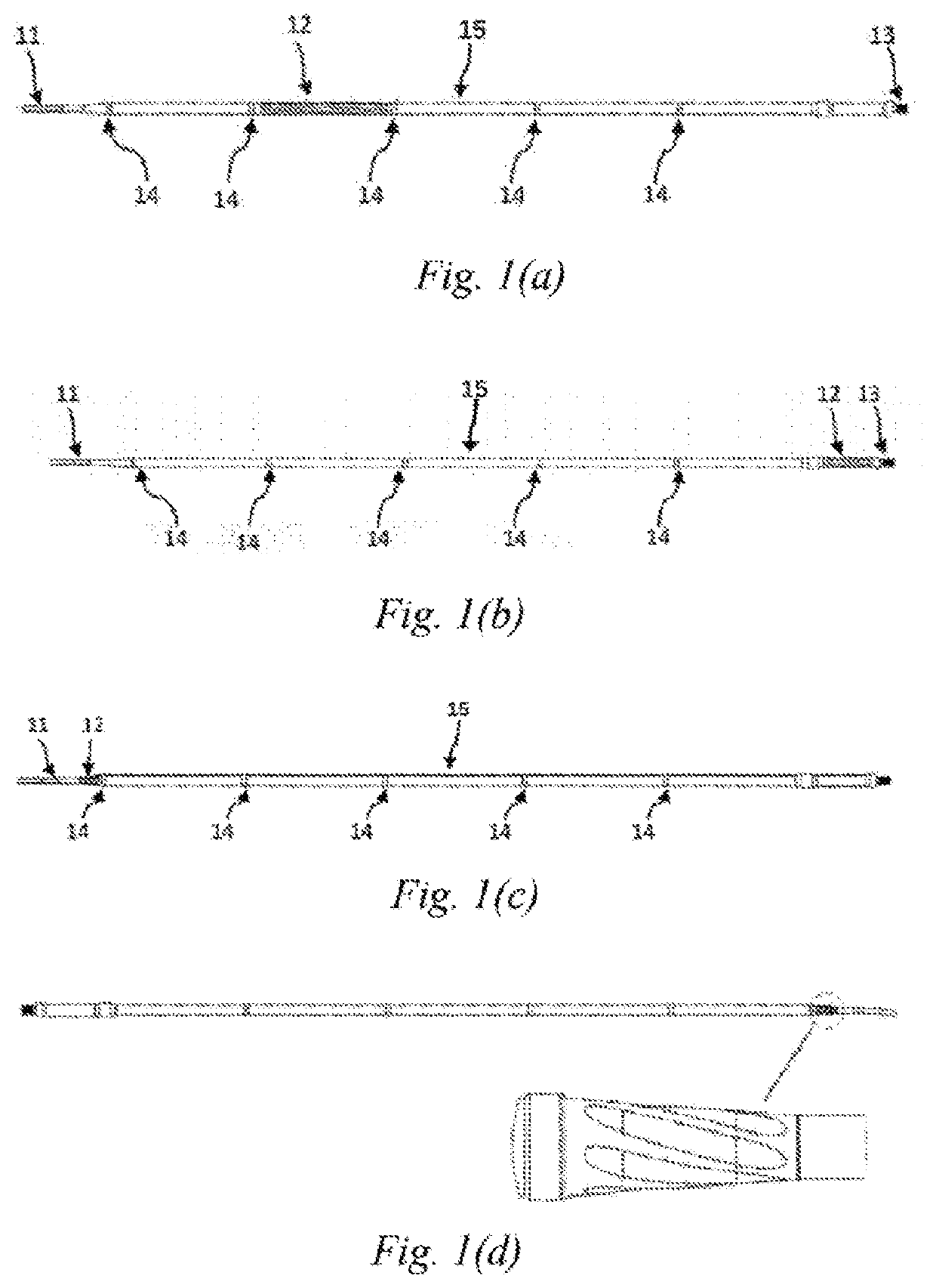
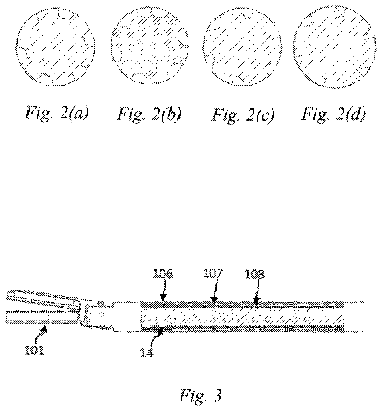
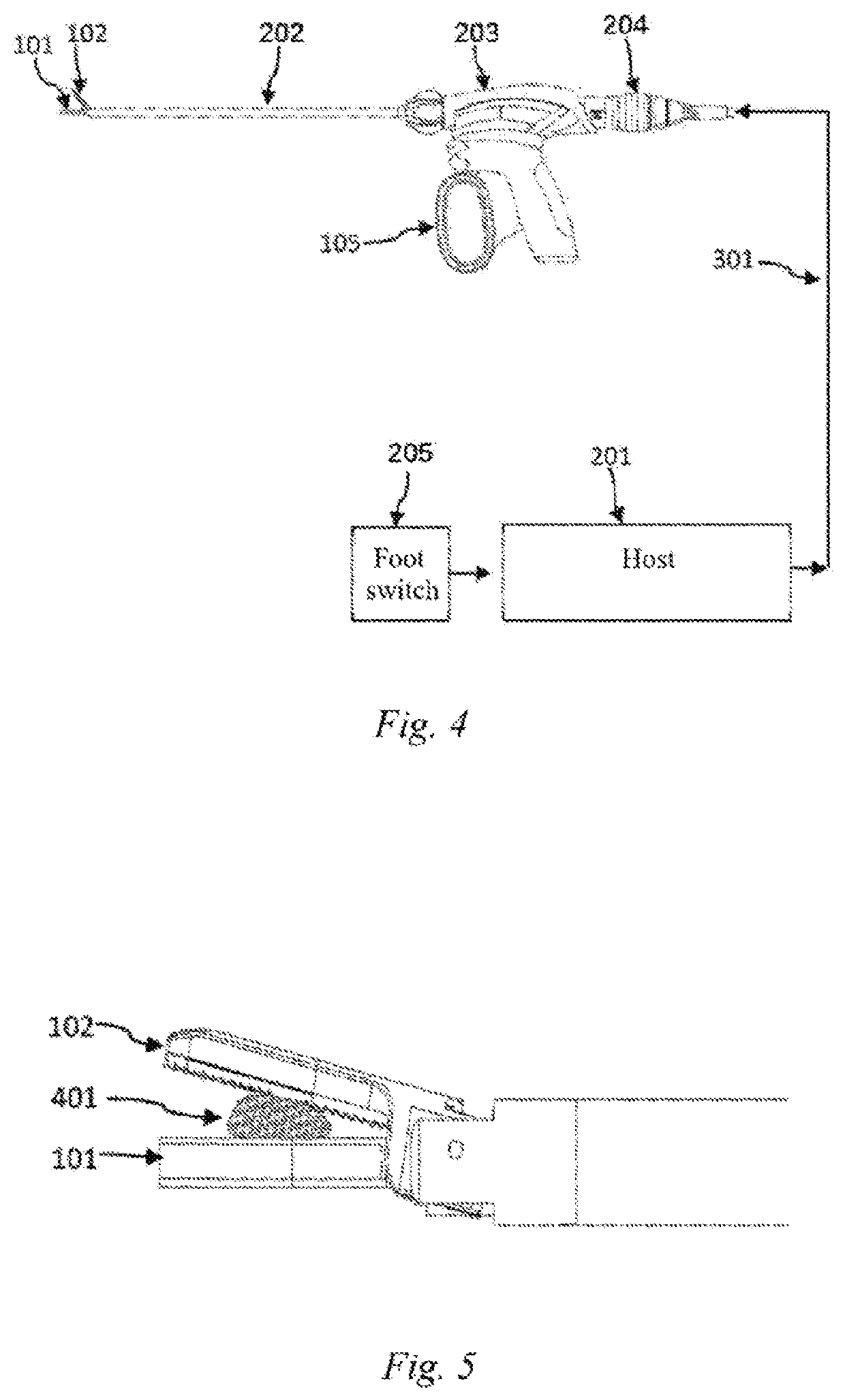
[0035]This embodiment discloses an ultrasonic scalpel bit 101, the structure of which is as shown in FIGS. 1(a), 1(b), 1(c), 6 and 8, comprising an ultrasonic scalpel tip 11, a waveguide 15, a connection portion 13 and vibration node bosses 14, wherein the ultrasonic scalpel tip 11 is arranged in front of the waveguide 15, the connection portion 13 is arranged behind the waveguide 15, the vibration node bosses 14 are arranged on the waveguide 15, the ultrasonic scalpel tip 11 is laterally bent at a pointed end thereof, and a vibration guide groove 12 is provided on the waveguide 15. Among the above components, the ultrasonic scalpel tip 11 is used to perform cutting and hemostasis operations on a biological tissue 401; the vibration guide groove 12 is used to convert a longitudinal vibration of an ultrasonic transducer into a longitudinal-torsional composite vibration; the connection portion 13 is used to connect the ultrasonic scalpel bit to the ultrasonic transducer to achieve con...

embodiment 2

[0040]As shown in FIG. 8, different from Embodiment 1 in which the vibration guide groove is provided on the waveguide 15, in this embodiment, the ultrasound guide groove 12 of the ultrasonic scalpel bit 101 is provided on the ultrasonic scalpel tip 11, and is located at a rear end of the ultrasonic scalpel tip 11. The frictional heat generation effect between the vibration guide groove 12 and the lubrication cylinder 108 can be further reduced by means of the above arrangement.

embodiment 3

[0041]This embodiment further defines the shape of the ultrasonic scalpel tip 11 of the ultrasonic scalpel bit 101 on the basis of Embodiment 1 or 2. That is, the ultrasonic scalpel tip 11 comprises a gradually-varying width in addition to being laterally bent at the pointed end thereof. For example, the gradually-varying width may be a trapezoidal gradually-varying width, a top view of which is as shown in FIG. 9(a) in which the front end of the ultrasonic scalpel tip 11 has a width larger than that of the rear end thereof, and a side view of which is as shown in FIG. 9(b). With the above design, the mass distribution law of the ultrasonic scalpel tip 11 along a vibration axis can be changed, such that the amplitude and pressure distribution characteristics of the ultrasonic scalpel tip 11 along the vibration axis are improved, further improving the temperature uniformity of the ultrasonic scalpel tip 11 during coagulation or cutting of the biological tissue 401, thereby improving ...


PUM


Abstract

Disclosed is an ultrasonic hemostasis and cutting system, comprising an ultrasonic vibration propagation assembly. An ultrasonic scalpel bit (101) of the ultrasonic vibration propagation assembly comprises an ultrasonic scalpel tip (11), a connection portion (13), vibration node bosses (14) and a waveguide (15), wherein the ultrasonic scalpel tip (11) is arranged in front of the waveguide (15), the connection portion (13) is arranged behind the waveguide (15), the vibration node bosses (14) are arranged on the waveguide (15), the ultrasonic scalpel tip (11) is laterally bent at a pointed end thereof, and a vibration guide groove (12) is further provided on the ultrasonic scalpel bit (101). By designing the ultrasonic scalpel bit in a bent shape and converting a longitudinal ultrasonic vibration into a longitudinal torsional composite vibration, temperature uniformity inside a tissue being cut or coagulated can be improved, thereby improving the efficiency and safety of hemostasis and cutting.

Description

TECHNICAL FIELD[0001]The present disclosure relates to the technical field of medical instruments, and in particular to an ultrasonic scalpel bit, an ultrasonic vibration propagation assembly, and an ultrasonic hemostasis and cutting system.BACKGROUND[0002]Compared with ordinary scalpels and other energy surgical instruments, ultrasonic hemostasis and cutting systems have advantages such as easy operation, small surgical trauma area, no smoke, less amount of bleeding, high precision of surgery, and quick postoperative recovery, and have been widely used in surgery.[0003]During coagulation or cutting, microscopic temperature uniformity of the ultrasonic hemostasis and cutting systems mainly depends on the temperature diffusion rate inside tissues and the uniformity of frictional heat generation caused by ultrasonic vibrations. Ultrasonic scalpel tips of existing ultrasonic hemostasis and cutting systems are straight cutters, and the ultrasonic scalpel bits only produce longitudinal v...

Claims


Application Information

Patent Timeline
Patent Type & Authority Applications(United States)
IPC IPC(8): A61B17/3211A61B17/32A61B18/04
CPCA61B18/04A61B17/3211A61B17/320068A61B17/320092A61B2017/320098A61B2017/320078A61B2017/320094A61B2017/320095A61B2017/320077A61B2017/00853A61B2017/00973A61B2017/00106A61B2018/00607A61B2018/0063
Inventor CAOHU, XIAOMINGZHAN, SONGTAOFENG, ZHENLI, CHUNYUAN
Owner BEIJING SMTP TECH CO LTD
Why Eureka
Try Eureka