Petroleum hydrocarbon feeding equipment

A technology of feeding equipment and petroleum hydrocarbons, applied in the direction of petroleum industry, cracking, chemical instruments and methods, etc., to achieve the effect of accelerating the heat exchange process, increasing the total surface area, and increasing the chance of contact

Active Publication Date: 2007-09-19
CHINA PETROLEUM & CHEM CORP +1
View PDF16 Cites 0 Cited by
  • Summary
  • Abstract
  • Description
  • Claims
  • Application Information

AI Technical Summary

Problems solved by technology

But up to now, the feeding device that the angle between the feeding direction and the vertical upward direction of the reactor axis is greater than 90° has not been reported.

Method used


Image

  • Petroleum hydrocarbon feeding equipment
  • Petroleum hydrocarbon feeding equipment
  • Petroleum hydrocarbon feeding equipment

Examples


Embodiment 1

[0030] This example illustrates that the present invention can make the catalyst particles contact with the hydrocarbon raw material instantaneously and evenly, thereby improving the product distribution.

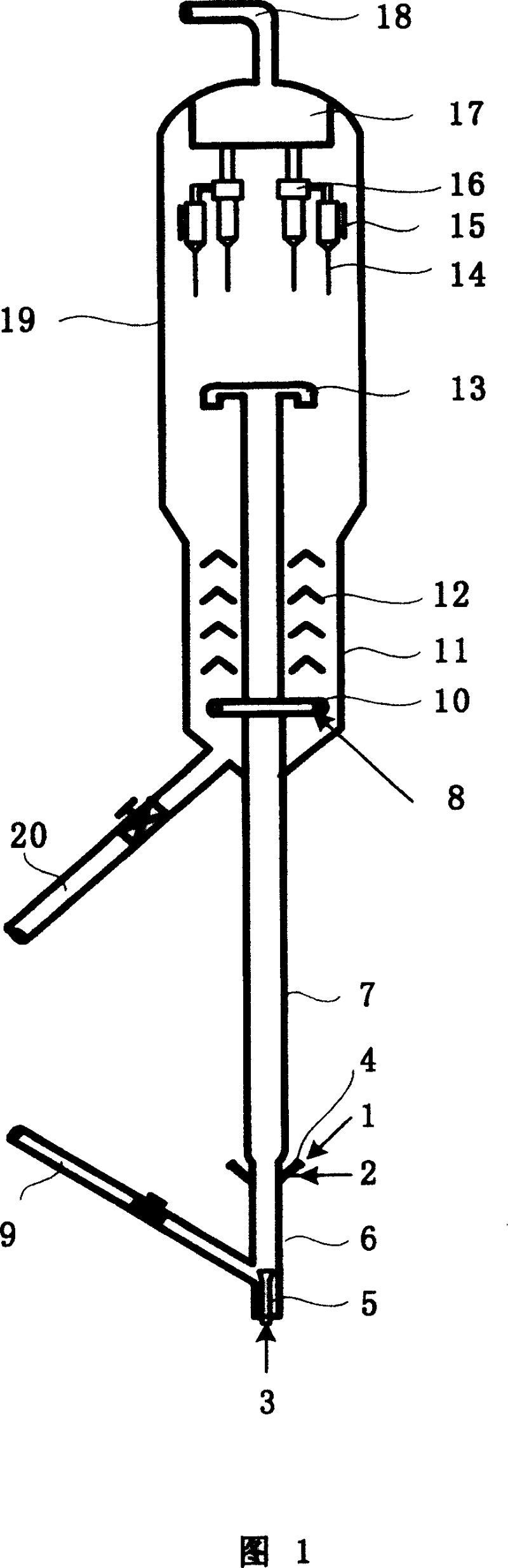
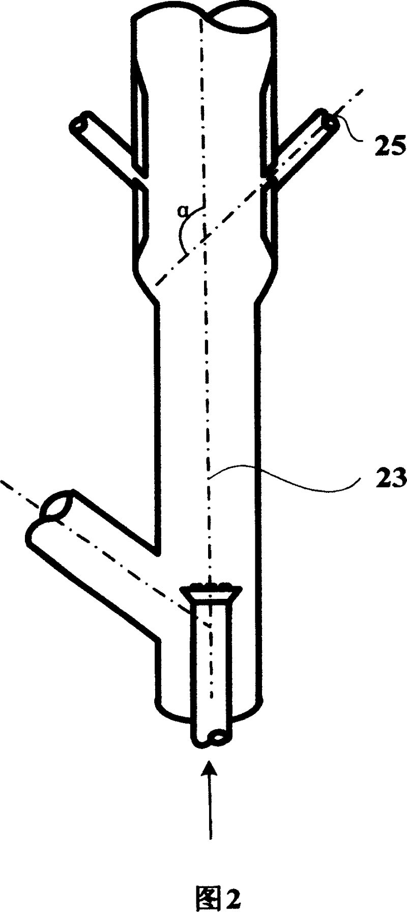
[0031] Experiments were carried out on a catalytic cracking medium-sized unit as shown in Figure 1. The main test steps are as follows: pre-lift steam is injected from the bottom of the riser reactor, and raw material A (its properties are shown in Table 1) is injected into the riser reactor through nozzle 4. The angle formed by the central axis of the nozzle 4 and the central axis of the riser reactor is 135°. The raw oil contacts and reacts with the regenerated catalyst MLC-500 (its properties are shown in Table 2), and the generated oil gas and the reacted catalyst enter the settler upward; the reaction oil gas and the reacted catalyst are separated, and the reaction oil gas is sent to the subsequent The separation system is further separated into various products; the ...

Embodiment 2

[0035] This example illustrates that the present invention can make the catalyst particles contact with the hydrocarbon raw material instantaneously and evenly, thereby improving the product distribution.

[0036] Experiments were carried out on a catalytic cracking medium-sized unit as shown in Figure 1. The main test steps are as follows: pre-lift steam is injected from the bottom of the riser reactor, and raw material A (its properties are shown in Table 1) is injected into the riser reactor through nozzle 4. The angle formed by the central axis of the nozzle 4 and the central axis of the riser reactor is 155°. The raw oil contacts and reacts with the regenerated catalyst MLC-500 (its properties are shown in Table 2), and the generated oil gas and the reacted catalyst enter the settler upward; the reaction oil gas and the reacted catalyst are separated, and the reaction oil gas is sent to the subsequent The separation system is further separated into various products; the ...


PUM


Abstract

The feeding device for petroleum hydrocarbon comprises a feeding nozzle and a connected riser reactor with included angel of their central axis in 80-180deg. This invention can improve product distribution and performance.

Description

technical field [0001] The present invention relates to a petroleum hydrocarbon feeding device, more specifically, a petroleum hydrocarbon feeding device used in a catalytic cracking process. Background technique [0002] In the catalytic cracking process, heavy macromolecular petroleum hydrocarbons are cracked into small molecular petroleum hydrocarbons. Typically, the preheated hydrocarbon feedstock is sprayed into one or more reaction zones after being atomized, where it contacts with a flow of fluidized catalyst particles and gasifies into oil and gas, and then the oil and gas molecules are generated under the action of the catalyst. cracking reaction. During the reaction process, coke, as one of the reaction products, gradually deposits on the surface of the catalyst particles, causing the catalyst to gradually lose its activity. After the carbon-containing catalyst is stripped of oil and gas, it burns off the coke and restores its activity in the oxygen-rich high-temp...

Claims


Application Information

Patent Timeline
Patent Type & Authority Patents(China)
IPC IPC(8): B01J8/18C10G11/00
Inventor 王巍张久顺龙军达志坚谢朝钢魏晓丽张春城
Owner CHINA PETROLEUM & CHEM CORP
Why Eureka
Try Eureka