Refrigerant supplying device

A technology for supplying devices and refrigerants, applied in refrigerators, refrigeration components, refrigeration and liquefaction, etc., can solve problems such as time-consuming, and achieve the effect of preventing excessive pressure rise, ensuring providing action, and efficient action.

Inactive Publication Date: 2007-09-19
AISIN SEIKI KK +2
View PDF8 Cites 0 Cited by
  • Summary
  • Abstract
  • Description
  • Claims
  • Application Information

AI Technical Summary

Problems solved by technology

Therefore, when the temperature is low in winter, etc., it takes time to pump up the refrigerant from the refrigerant container 31 compared to when the temperature is high in summer, etc.

Method used


Image

  • Refrigerant supplying device
  • Refrigerant supplying device
  • Refrigerant supplying device

Examples


Embodiment Construction

[0036] Hereinafter, an embodiment of the refrigerant supply device according to the present invention will be described in detail with reference to the drawings.

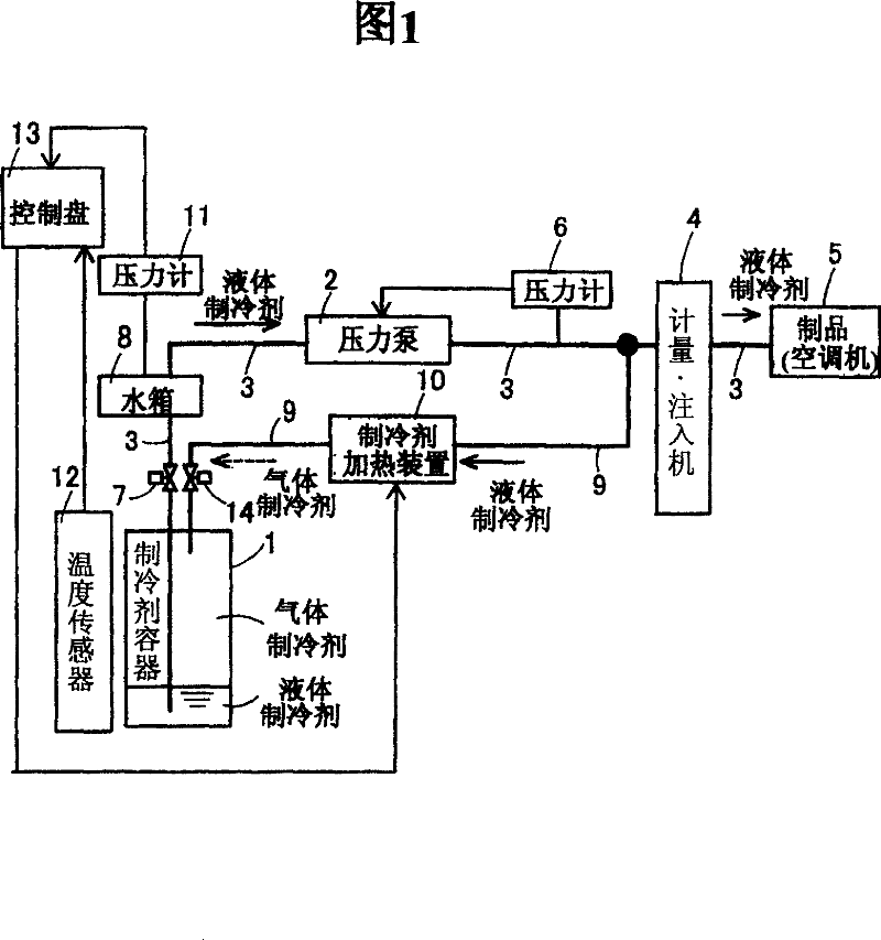
[0037] FIG. 1 shows a schematic configuration diagram of a refrigerant supply device according to this embodiment. In this refrigerant supply device, the liquid refrigerant in the refrigerant container 1 is pumped by the pressure pump 2, passes through the supply pipe 3 and the metering / injecting machine 4, and is supplied and filled to a product (air conditioner) 5 as consumer equipment. The refrigerant supply device has a first pressure gauge 6 for measuring the pressure (discharge pressure) of the liquid refrigerant in the supply pipe 3 on the downstream side of the pressure pump 2 . The discharge pressure measured by the first pressure gauge 6 is sent to the pressure pump 2 as a control signal. In this embodiment, when the discharge pressure measured by the first pressure gauge 6 is lower than a predetermined s...


PUM


Abstract

The purpose of this invention is to increase the heating efficiency of a liquid refrigerant by relatively reducing the size of a structure for filling a refrigerant container with a gas refrigerant. This refrigerant feeder force-feeds the liquid refrigerant in the refrigerant container 1 by a force-feed pump 2 to supply the liquid refrigerant to a product 5 through a supply pipe 3. A return pipe 9 leading to the refrigerant container 1 after branching from the supply pipe 3 is installed on the downstream side of the force-feed pump 2. The liquid refrigerant flowing in the return pipe 9 is heated and evaporated by a heater contained in a refrigerant heating device 10, and the evaporated gas refrigerant is depressed by a pressure reducing valve contained in the device 10. A pressure gauge 11 measuring a refrigerant pressure in a header is installed in the header 8 installed in the supply pipe 3. A temperature sensor 12 detecting the temperature of the refrigerant container 1 is installed in the refrigerant container. A control panel 13 controls the heater 15 based on the detected refrigerant pressure and the temperature of the container.

Description

technical field [0001] The present invention relates to a refrigerant supply device used for filling refrigerant into cooling equipment such as an air conditioner. Background technique [0002] Conventionally, in a refrigerant container that accommodates refrigerant filled in a cooling device such as an air conditioner, the refrigerant is divided into a liquid layer and a gas layer. The state of the liquid layer and the gas layer coincides with the saturated vapor pressure corresponding to the ambient temperature. Here, in order to fill the cooling device with the refrigerant in the refrigerant container, the refrigerant is sucked up from the refrigerant container. At this time, as shown in FIGS. 6( a ) and ( b ), the refrigerant container 31 absorbs heat from its surroundings, and the liquid refrigerant vaporizes in the refrigerant container 31 . That is, the level of liquid refrigerant (liquid layer) decreases and the volume of gas refrigerant (gas layer) increases as li...

Claims


Application Information

Patent Timeline
Patent Type & Authority Patents(China)
IPC IPC(8): F25B45/00
CPCF25B45/00F25B2313/008F25B2400/01F25B2700/21F25B2700/19F25B41/40F25B41/20
Inventor 多田诚铃木茂之高桥外茂雄
Owner AISIN SEIKI KK
Why Eureka
Try Eureka