Optical fibre current transformer and its loop detector of transformer

A technology of closed-loop detection and fiber optic current, which is applied in the directions of measuring devices, voltage/current isolation, measuring current/voltage, etc., can solve the problems of small dynamic range, complex insulation structure, large insertion loss, etc., and achieve small influence of electromagnetic interference and dynamic Wide range and good insulation performance

Inactive Publication Date: 2007-10-03
BEIHANG UNIV
View PDF3 Cites 2 Cited by
  • Summary
  • Abstract
  • Description
  • Claims
  • Application Information

AI Technical Summary

Problems solved by technology

[0003] (1) The increase of the voltage level increases the difficulty of insulation, resulting in complex insulation structure, larger volume and weight, inconvenient installation and transportation, and the cost rises exponentially
[0004] (2) Due to the limited magnetic characteristics of the iron core, the iron core may be seriously saturated under the action of some large operating current or fault current, which will cause unacceptable deviations in the measurement results and provide wrong information to the power system
[0005] (3) If the transformer output is in an open circuit state, the output terminal will induce high voltage, which may cause insulation failure or endanger the safety of other equipment and staff
[0006] (4) At present, the interior of traditional current transformers is mostly filled with mineral oil as the insulation and heat dissipation medium, and there is a danger of sudden failure that may cause combustion and explosion
The defects of fiber optic current transformers constructed of crystals are: small dynamic range, low sensitivity, and large insertion loss

Method used


Image

  • Optical fibre current transformer and its loop detector of transformer
  • Optical fibre current transformer and its loop detector of transformer
  • Optical fibre current transformer and its loop detector of transformer

Examples


Embodiment Construction

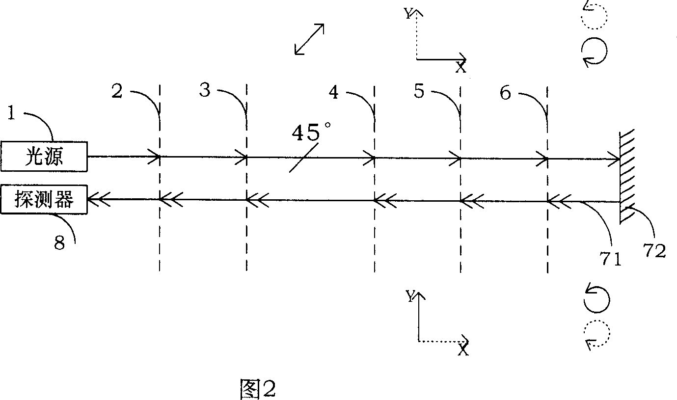
[0026] The essence of the fiber optic current transformer with all-fiber structure is measured by the principle of two beams of light interference. The magnetic field is generated due to the transmission current in the sensing fiber. When a beam of circularly polarized light passes through the sensing fiber, the phase of the circularly polarized light changes due to the Faraday effect, and the phase change is Δθ. By measuring two coherent beams of light, the current value in the wire can be measured indirectly.

[0027] (1) Hardware structure of all-fiber-optic current transformer

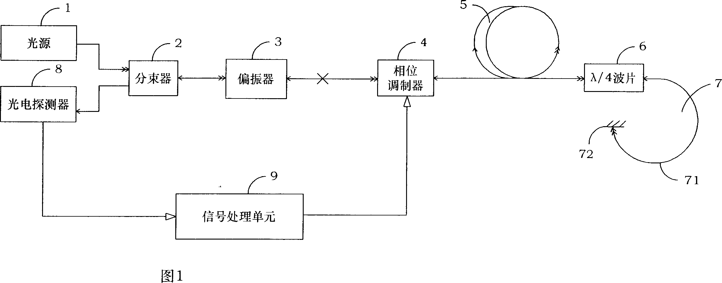
[0028] Please refer to shown in Fig. 1, the present invention is a kind of optical fiber current transformer, by light source 1, photodetector 8, sensing head 7, it is characterized in that: also comprise beam splitter 2, polarizer 3, phase modulator 4 , a polarization-maintaining delay cable 5, a λ / 4 wave plate 6 and a signal processing unit 7, the sensor head 7 is formed by a sensor fiber 71 coa...


PUM


Abstract

This invention publishes a kind of fiber optic current transformer and its closed loop checking device. In the fiber optic current transformer the beam paths are all linked with the fibers and the circuit uses the closed loop checking module The light intensity voltage signal outputted form the electrophotonic detector is absorbed by the forth unit in the closed loop checking device, and after A / D conversion it is send to FPGA. FPGA will send the voltage signals to DSP, which will do the digital demodulation, number filtration and the integral treatment and then send the control signal to FPGA. Then FPGA send the control signal to the analogue output circuit, and meanwhile the square wave modulation circuit and the digital step wave producing circuit will get the control signal from FPGA. After added together, the square wave signal and the digital step wave height signal will drive the phase modulation machine. This invention use the whole-optical-fiber to transmit signals, having good insulativity and little affected by the electromagnetic interference. The measuring frequency range is wide and has large dynamic dimension. What is more, it use the closed loop checking device, so the open circuit and the high pressure will not appear.

Description

technical field [0001] The invention relates to a sensor device, in particular to an optical fiber current transformer with an all-fiber structure. The fiber optic current transformer uses the Faraday effect of the magnetic field generated by the transmission current to change the phase of the transmission light, and the current value in the wire can be indirectly measured by measuring the signal amplitude after interference. Background technique [0002] Current transformer (CT for short) is an important device for electric energy measurement and relay protection in the power system. Its accuracy and reliability are closely related to the safe, reliable and economical operation of the power system. However, with the development of the power industry, the capacity of the power transmission system continues to increase, and the operating voltage level is getting higher and higher. At present, the highest voltage level of my country's power grid has reached 500KV, and it is de...

Claims


Application Information

Patent Timeline
Patent Type & Authority Patents(China)
IPC IPC(8): G01R15/24G01R19/00
Inventor 张春熹王夏霄张朝阳袁玉厂姜中英
Owner BEIHANG UNIV
Why Eureka
Try Eureka