


Quick Research
Generate reliable direction feasibility study reports for your R&D in just a few steps.

Technical Q&A
Discover and master advanced knowledge NOW. Basics, ideas, possibilities, all at once.

Find Solutions
As an expert in R&D theories, this can generate solutions to your technical problems instantly.

Evaluate Feasibility
Analyze your overall solution with one click, know your potential R&D risks in advance.

Monitor Landscape
Get weekly tech updates, stay abreast of the latest tech innovations and key insights.
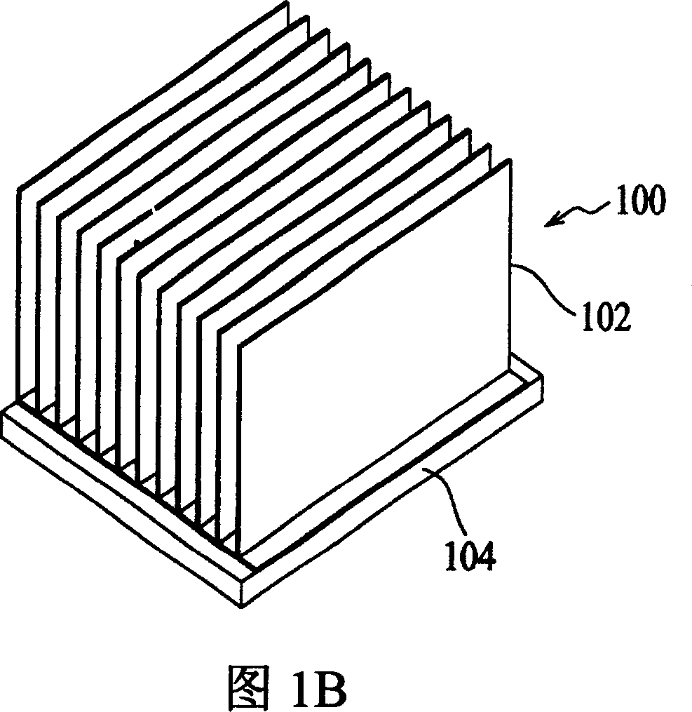
Radiating fin and fin assembly
A technology of heat dissipation fins and fins, which is applied in the direction of electrical components, heat exchange equipment, electric solid devices, etc., can solve the problems of affecting welding quality, retention, increase in contact thermal resistance between heat dissipation fins and substrates, etc., and maintain stability , reduce contact thermal resistance, improve the effect of welding quality
- Summary
- Abstract
- Description
- Claims
- Application Information
AI Technical Summary
Problems solved by technology
Method used
Image

Examples
Embodiment Construction
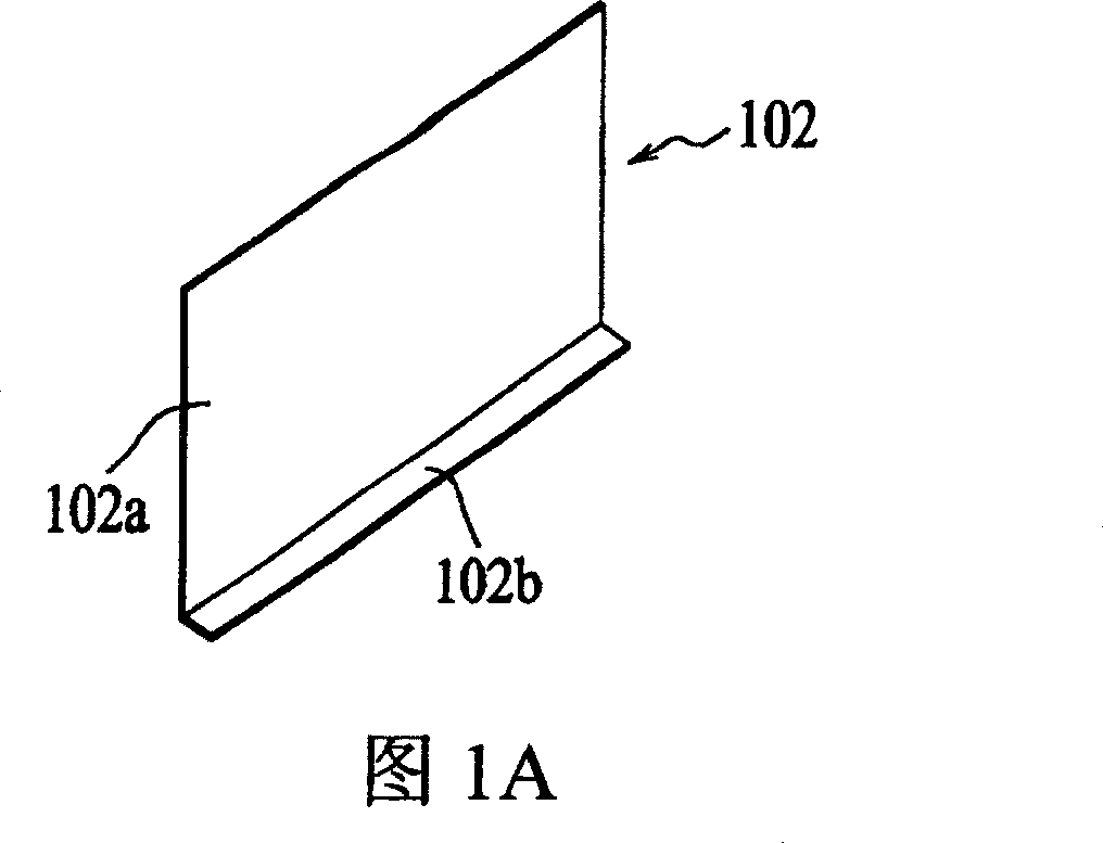
[0018] FIG. 2A is a perspective view showing the structure of the heat dissipation fin 12 according to an embodiment of the present invention.
[0019] As shown in FIG. 2A , the heat dissipation fins 12 are formed by bending a sheet of heat-conducting material into an L-shaped cross-section, and include a large-area heat dissipation portion 12 a and an elongated welding portion 12 b. The sheet-shaped heat-conducting material can be bent to form the welding portion 12b by means of sheet metal processing, and the heat-conducting material can be a high-heat-conducting material composed of aluminum, copper, aluminum alloy, copper alloy, or a mixture thereof.
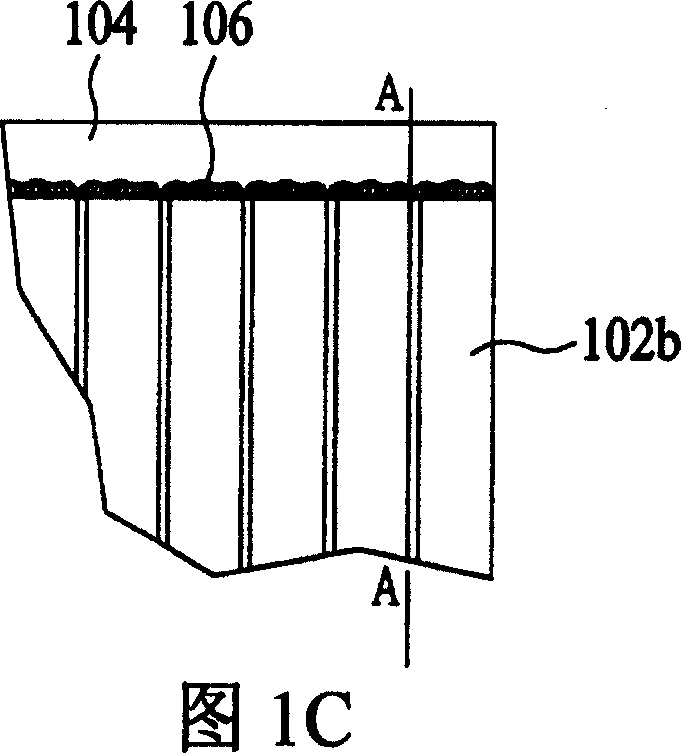
[0020] According to the design of the present invention, the welding portion 12b has a plurality of notches 14 formed by the edge of the sheet-shaped heat-conducting material inwardly toward the bend. The shape of the notches 14 can be in any form, and the number is not limited. Portion 12b has a serrated edge. Therefore, w...
PUM
 Abstract
Description
Claims
Application Information
 - R&D Engineer
- R&D Manager
- IP Professional
- Industry Leading Data Capabilities
- Powerful AI technology
- Patent DNA Extraction
Browse by: Latest US Patents, China's latest patents, Technical Efficacy Thesaurus, Application Domain, Technology Topic, Popular Technical Reports.
© 2024 PatSnap. All rights reserved.Legal|Privacy policy|Modern Slavery Act Transparency Statement|Sitemap|About US| Contact US: help@patsnap.com