Eureka AIR delivers breakthrough ideas for toughest innovation challenges, trusted by R&D personnel around the world.

Method for setting lens module and structure

A lens module and installation method technology, applied in installation, color TV parts, TV system parts and other directions, can solve the problems of lack of structure, hinder production cost, reduce the product, etc., to improve the installation method and improve the quality rate, reducing the effect of noise interference

Inactive Publication Date: 2007-11-07
HONG FU JIN PRECISION IND (SHENZHEN) CO LTD +1
View PDF5 Cites 1 Cited by
  • Summary
  • Abstract
  • Description
  • Claims
  • Application Information

AI Technical Summary

Problems solved by technology

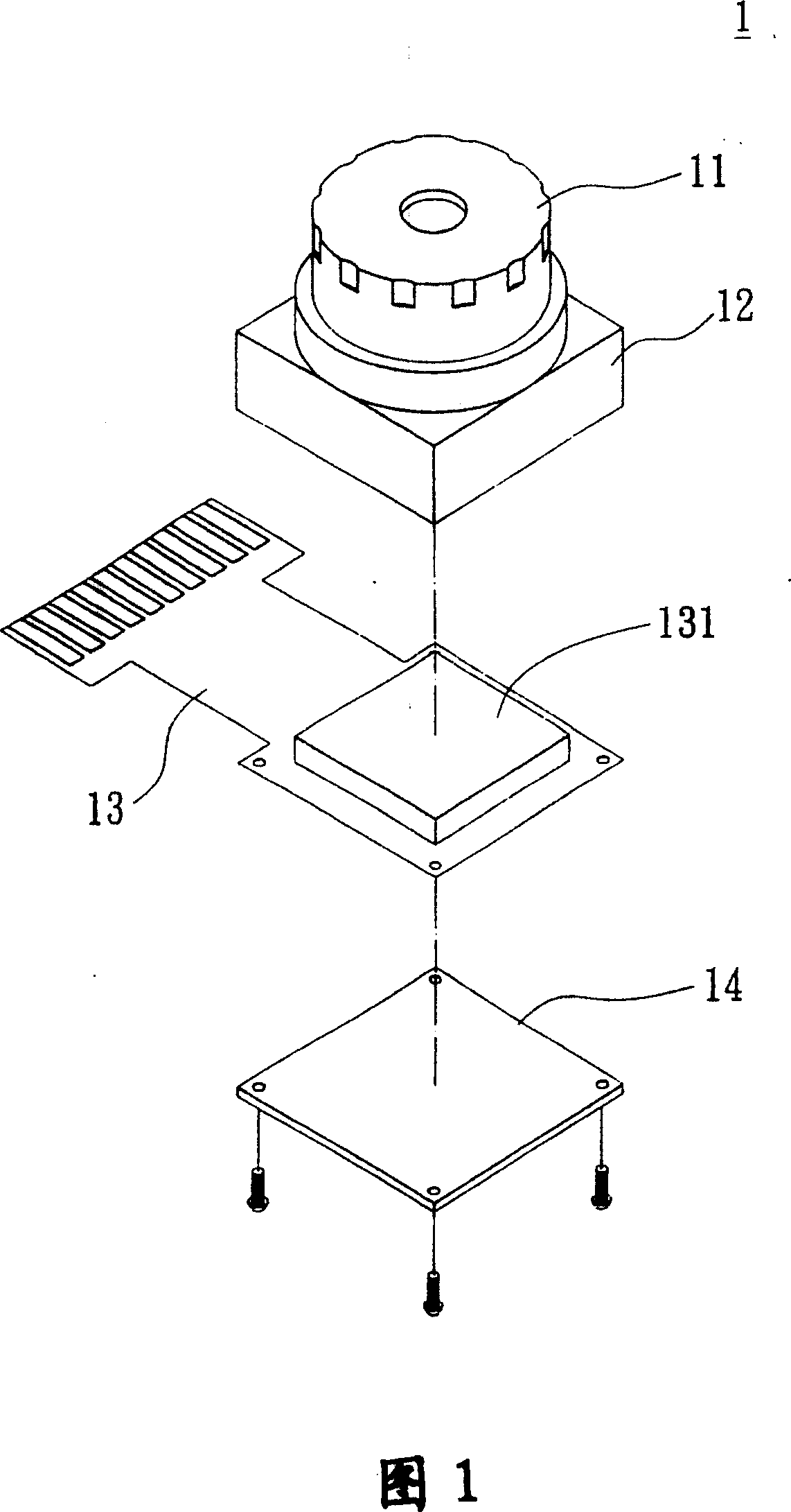
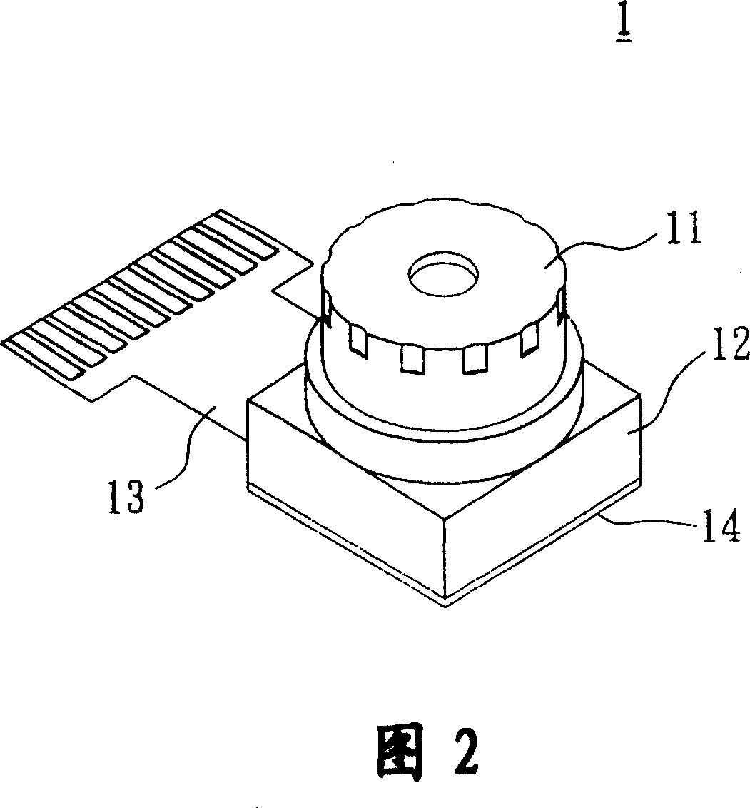
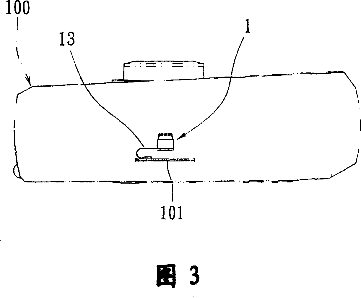
[0004] Since the existing known lens module 1 must use a flexible printed circuit board (FPCB) 13 to transmit image signals, it cannot be directly assembled on the circuit board of an electronic product in an automated mass production manner, which hinders its production cost. reduction of
[0005] It can be seen that the installation method and the structure of the above-mentioned existing lens module obviously still have inconvenience and defects in actual manufacture and use, and need to be further improved urgently.
In order to solve the problems of the installation method and structure of the lens module, the relevant manufacturers have tried their best to find a solution, but for a long time no suitable design has been developed, and there is no suitable structure for general products. The above-mentioned problems are obviously the problems that relevant industry players are eager to solve

Method used


Image

  • Method for setting lens module and structure
  • Method for setting lens module and structure
  • Method for setting lens module and structure

Examples


Embodiment Construction

[0068] In order to further explain the technical means and effects of the present invention to achieve the intended purpose of the invention, in conjunction with the accompanying drawings and preferred embodiments, the specific installation method and structure of the lens module according to the present invention will be described. Steps, structures, features and effects thereof are described in detail below.

[0069] Please refer to Fig. 4 to Fig. 7, Fig. 4 is an exploded perspective view of the lens module of the present invention, Fig. 5 is a sectional view of a partial assembly structure of the lens module of the present invention, and Fig. 6 is a diagram of the module body in the lens module of the present invention Bottom view, FIG. 7 is a three-dimensional schematic diagram of the combined structure of the lens module of the present invention.

[0070] The structure of the lens module 200 implemented according to the present invention may include a module body 2 and a ...


PUM


Abstract

A camera lens module consists of module body including camera lens unit, image induction processing unit and signal terminal as well as base including signal terminal set. Its installing method includes applying surface mounting technique to connect base on circuit board of an electronic appliance, connecting module body on base to let light enter image induction processing unit for forming image signal through camera unit and to send image signal to said circuit board through base terminal set.

Description

technical field [0001] The present invention relates to a method for installing a lens module and its structure, in particular to an adapter base that can be connected to a circuit board of an electronic product by surface mount technology (SMT). , and then connect the module body of the lens module to the matching base, so that the electrical signal generated by the lens module can be connected to the installation method and structure of the lens module on the circuit board. Background technique [0002] At present, lens modules that are mass-produced in modules and used in "electronic products with camera functions (such as digital cameras, mobile phones with camera functions, or PDAs with camera functions)" often have defects. The phenomenon of high rate is analyzed as follows: [0003] Please refer to Fig. 1, Fig. 2, and Fig. 3. Fig. 1 is an exploded perspective view of a known lens module, Fig. 2 is a perspective combination diagram of a known lens module, and Fig. 3 i...

Claims


Application Information

Patent Timeline
Patent Type & Authority Patents(China)
IPC IPC(8): G02B7/02H04N5/225
Inventor 龙建立
Owner HONG FU JIN PRECISION IND (SHENZHEN) CO LTD
Why Eureka
Eureka Blog
Learn More