Method and apparatus for transmitting signal via base station power emission channel
A transmission channel and signal transmission technology, which is applied in power management, device selection, wireless communication, etc., can solve problems such as waste of system resources, unbalanced use efficiency, interruption of transmission signals, etc., and achieve low power consumption requirements, improved reliability, and use The effect of improving efficiency
- Summary
- Abstract
- Description
- Claims
- Application Information
AI Technical Summary
Problems solved by technology
Method used
Image
Examples
Embodiment 1
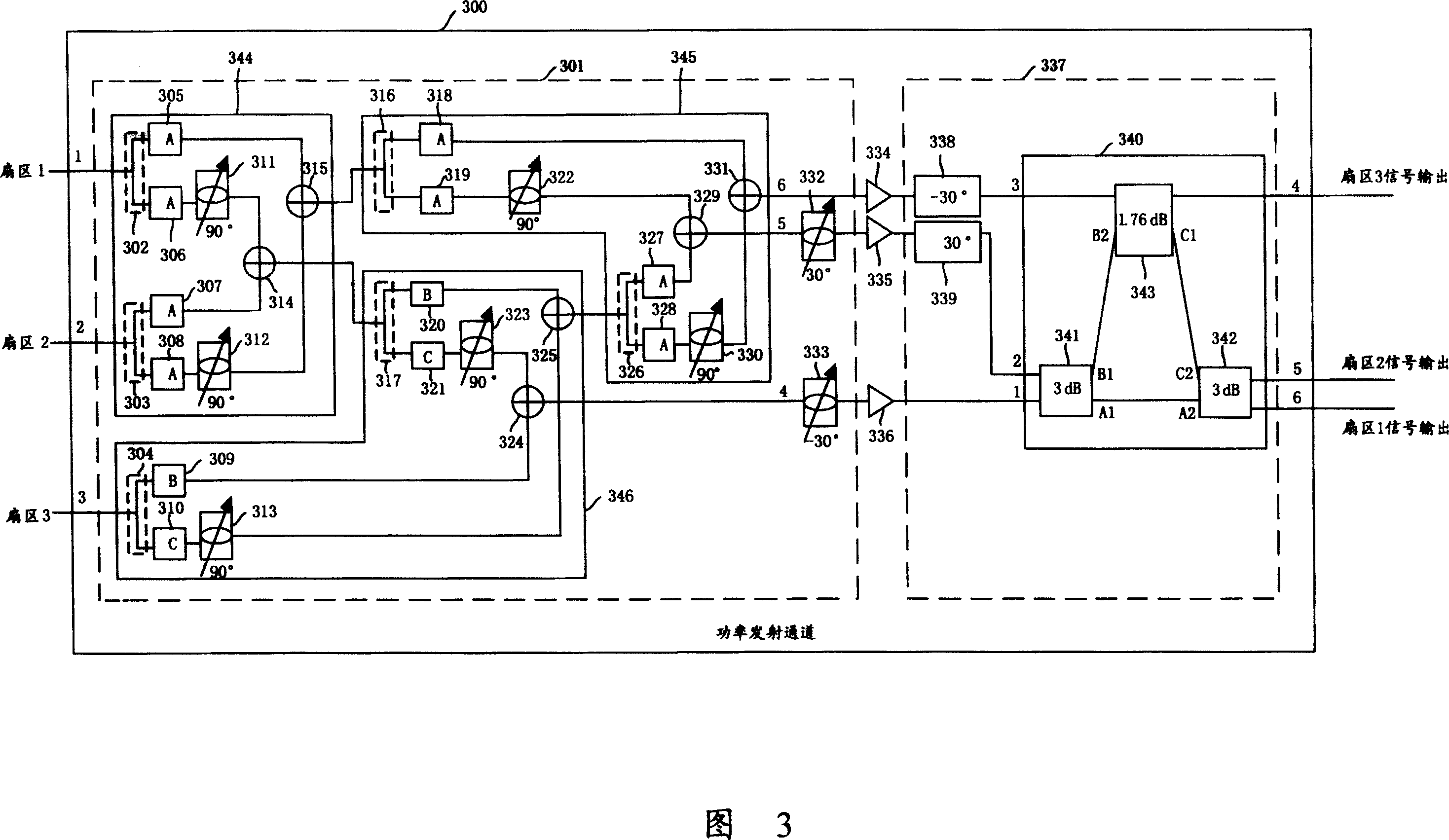
[0085] Embodiment 1: 3-sector base station power transmission channel
[0086] As shown in FIG. 3 , the power transmitting channel 300 is composed of a digital matrix 301 , digital signal power amplifiers 334 , 335 , 336 and a hybrid bridge matrix 337 .
[0087] The digital matrix 301 includes a first mixing unit 344 , a second mixing unit 345 , a third mixing unit 346 , a digital signal 30-degree phase shifter 332 and a digital signal negative 30-degree phase shifter 333 .
[0088] Wherein, the first mixing unit 344 includes digital signal duplicators 302, 303 and 1 / 2 digital signal limiters 305, 306, 307, 308, and also includes digital signal 90-degree phase shifters 311, 312 and digital signal combiner 314,315; the second mixing unit 345 includes digital signal duplicator 316,326 and 1 / digital signal limiter 318,319,327,328, also includes digital signal 90 degree phase shifter 322,330 and digital signal combiners 329, 331; the third mixing unit 346 includes digital signa...
Embodiment 2
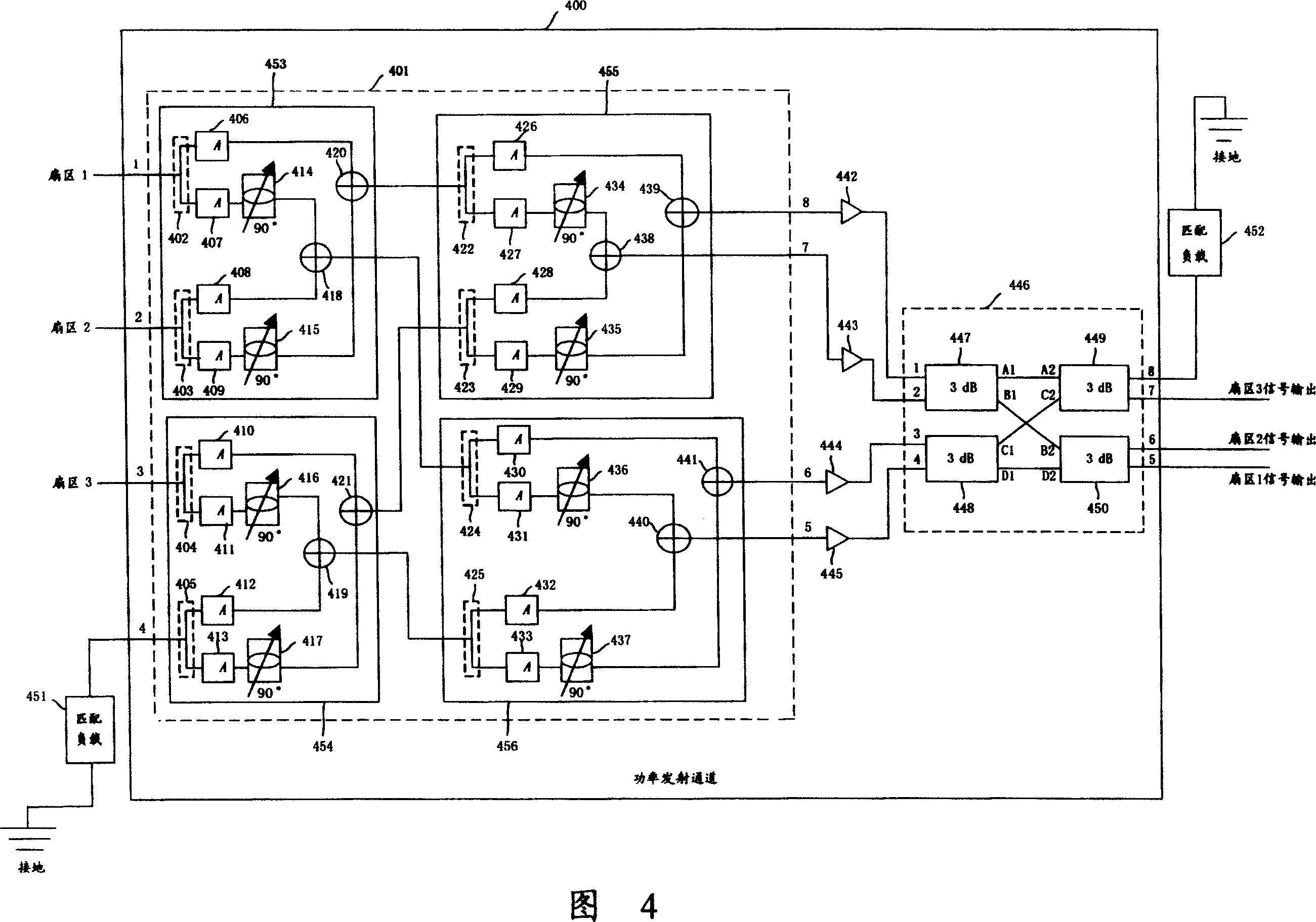
[0170] Embodiment 2: 3 sectors back up one power amplifier base station power transmission channel
[0171] In some important occasions, in order to ensure the stable load and normal working efficiency of the power transmission channel, a digital signal power amplifier is backed up and controlled by a switch; when a digital signal power amplifier fails, the digital signal is temporarily backed up The power amplifier does its job. The backup situation of general digital signal power amplifier is to carry out the backup of one digital signal power amplifier to the power transmission channel of 3 digital signal power amplifiers, make it become the power transmission channel with 4 digital signal power amplifiers.
[0172] As shown in FIG. 4 , the power transmitting channel 400 is composed of a digital matrix 401 , digital signal power amplifiers 442 , 443 , 444 , 445 and a hybrid bridge matrix 446 . Wherein, the digital matrix 401 includes a first mixing unit 453, a second mixin...
Embodiment 3
[0205] Embodiment 3: 4-sector base station power transmission channel
[0206] As shown in Figure 5, the principle of signal transmission in this embodiment is the same as that in Embodiment 2. The only difference between the two embodiments is that in Embodiment 2, at the front end of the power transmission channel, some signal input The port has no sector signal input, but is connected to a grounded matching load; correspondingly, at the rear end of the power transmission channel, the output port corresponding to the port connected to the matching load at the front end of the power transmission channel is also connected to a grounded matching load, and there is no Sector signal output. In this embodiment, each signal input port at the front end of the power transmission channel has a sector signal input; correspondingly, at the rear end of the power transmission channel, the output ports corresponding to each input port at the front end of the power transmission channel have...
PUM
 Abstract
Description
Claims
Application Information
 - R&D
- Intellectual Property
- Life Sciences
- Materials
- Tech Scout
- Unparalleled Data Quality
- Higher Quality Content
- 60% Fewer Hallucinations
Browse by: Latest US Patents, China's latest patents, Technical Efficacy Thesaurus, Application Domain, Technology Topic, Popular Technical Reports.
© 2025 PatSnap. All rights reserved.Legal|Privacy policy|Modern Slavery Act Transparency Statement|Sitemap|About US| Contact US: help@patsnap.com


