
Brush for rotary dental hand held tool

A hand-held appliance, dental technology, applied in the direction of dental tools, dental, home appliances, etc., can solve the problem of not being able to fully contact the gap

Inactive Publication Date: 2007-12-19
科瑞华公司
View PDF8 Cites 0 Cited by
  • Summary
  • Abstract
  • Description
  • Claims
  • Application Information

AI Technical Summary

Problems solved by technology

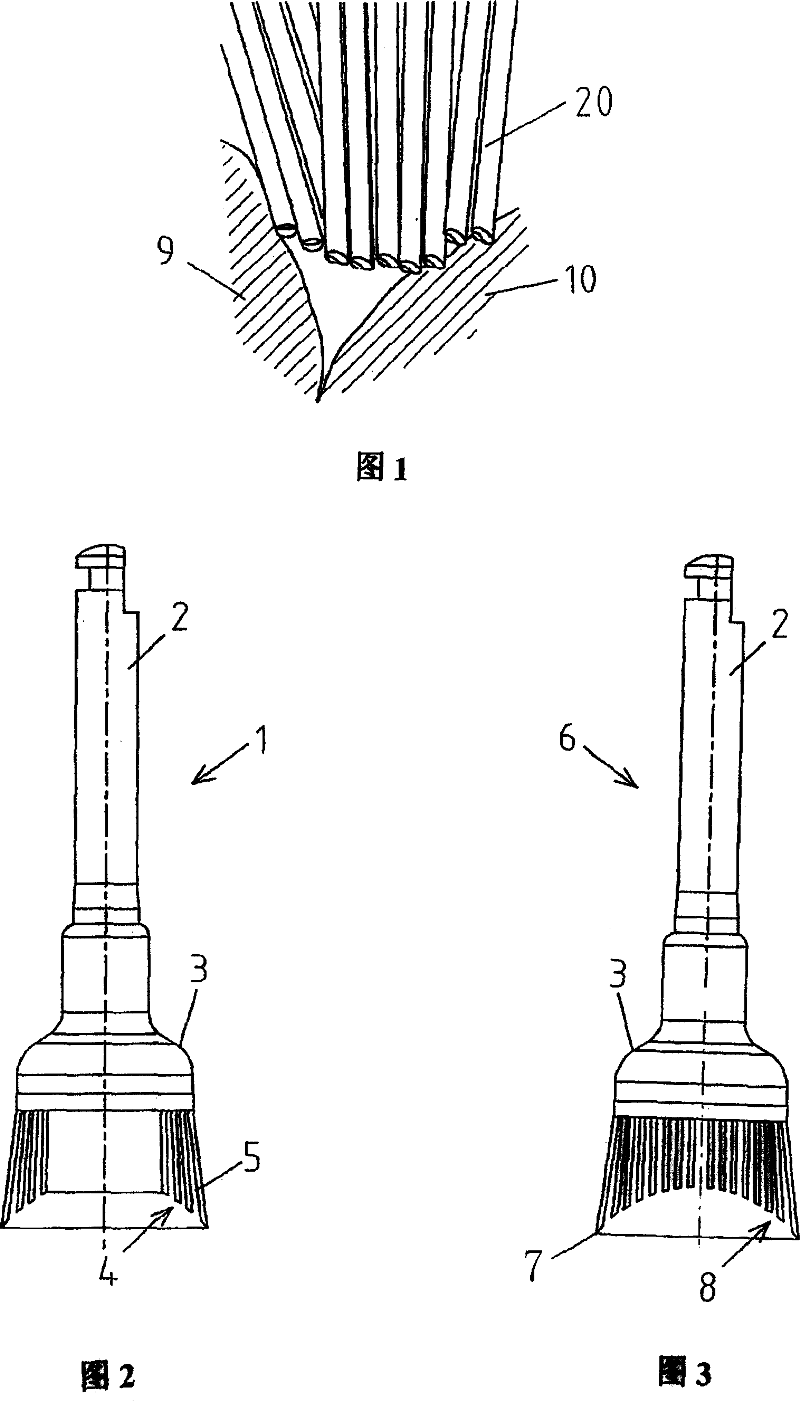
[0005] The disadvantage of this arrangement of bristles is that they do not adequately reach the voids and do not allow thorough finishing, buffing, grinding or cleaning of particularly narrow crevices and crevices, as shown in Figure 1

Method used


Image

  • Brush for rotary dental hand held tool
  • Brush for rotary dental hand held tool
  • Brush for rotary dental hand held tool

Examples


Embodiment Construction

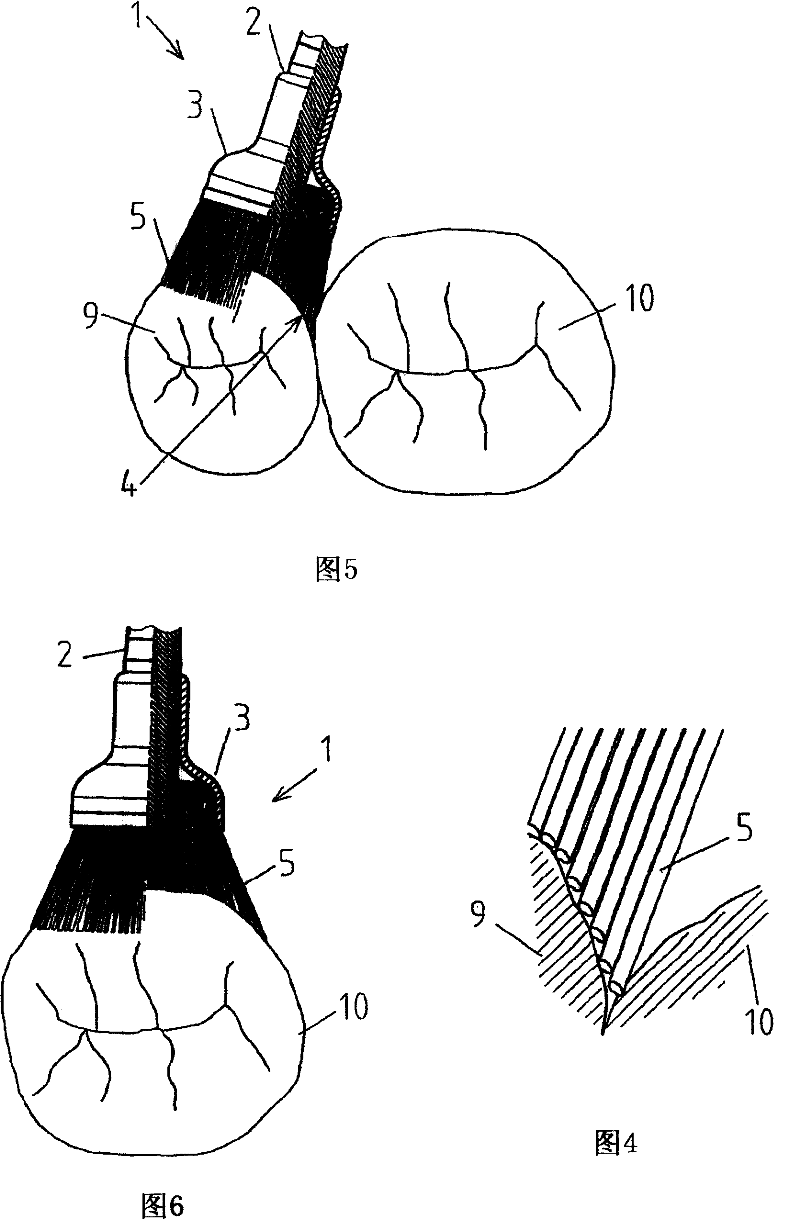
[0015] It can be seen from FIG. 1 that the bristles 20 do not penetrate sufficiently into the spaces between the teeth 9 and 10 or into the crevices. On the contrary, as shown in FIG. 4 , the bristles 5 or 7 of the brush of the present invention can penetrate deep into voids and crevices.

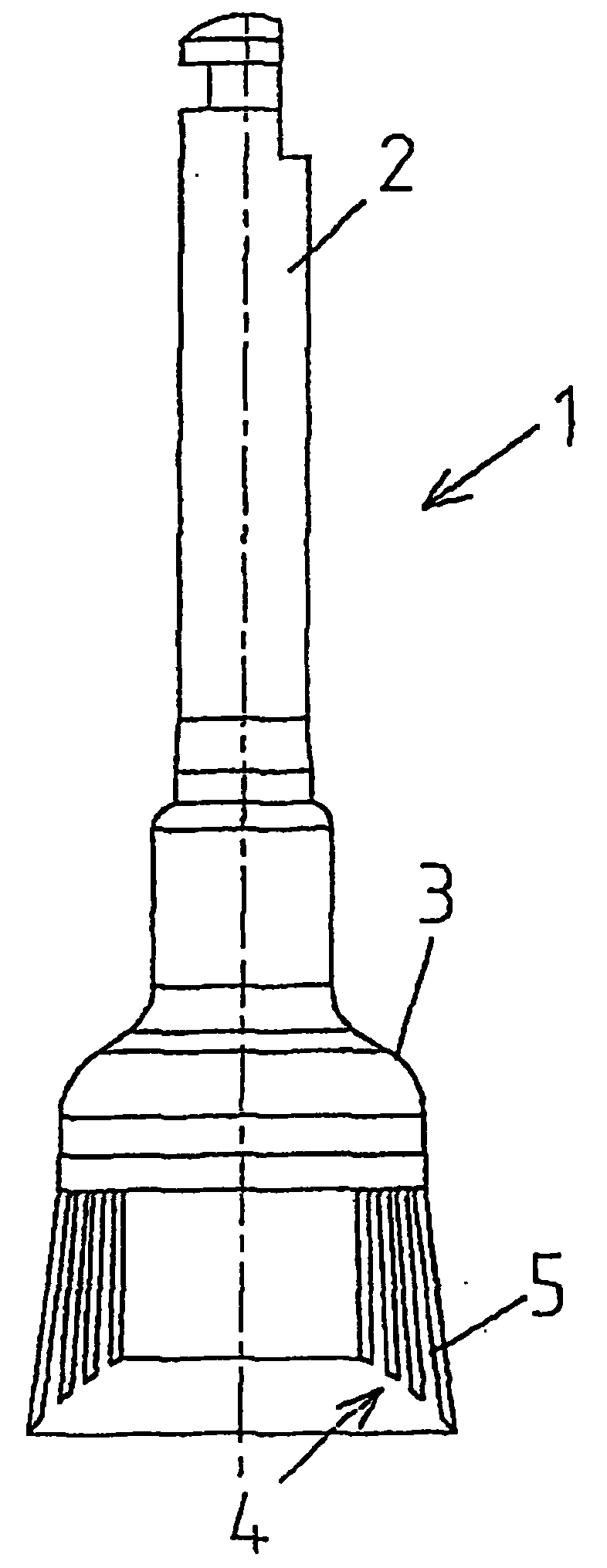
[0016] The brush 1 according to the invention shown in FIG. 2 basically comprises a fastening part 2 for fixing it on a rotating dental handpiece, and a brush head 3 with a bristle field 4 formed by individual bristles 5 . As shown in Fig. 2 and Fig. 4 to Fig. 6, the bristles of this exemplary embodiment are arranged in a crown shape, and the length of the bristles gradually decreases from the outer to the center of the bristles, ie, forms a concave shape.

[0017] This reduction can be linear or form an arc, ie spherical or correspond to another geometric shape. Depending on the purpose of use, the individual bristles 5, which may be round, may consist of abrasive materials such as alumin...


PUM


Abstract

The brush for use on a dental rotary hand piece comprises a bristle field in which the length of the bristles decreases from the external radius of the bristle field towards its center. A brush of this kind allows improved finishing, polishing, and cleaning of interdental spaces and fissures in the chewing surface.

Description

technical field [0001] The present invention relates to a dental brush having a bristle field for use with rotating dental handpieces or electric toothbrushes. Various rotating brushes are known in the art for finishing, buffing and cleaning teeth and / or fillings. The bristle field of these brushes, produced with several individual bristles, can be designed in various forms and can, for example, consist entirely or only of crown-shaped bristles. Background technique [0002] Currently, brushes have been successfully used instead of rotary polishers, thus on the one hand reducing the number of operations required after diamond finishing and ideally allowing the use of a single polishing tool for all tooth surfaces, regardless of their geometry or accessibility. [0003] US-A-4020522 and US-A-4739532 are mentioned here as examples of crown-shaped arrays of bristles whose length decreases from the inside to the outside of the bristle field. This brush is mainly used in the d...

Claims


Application Information

Patent Timeline
Patent Type & Authority Patents(China)
IPC IPC(8): A61C17/22A61C17/00A46B9/04A46B13/00A61C3/06
CPCA61C3/06A61C17/222A46B9/028A46B13/008
Inventor 斯蒂芬·齐默
Owner 科瑞华公司
Learn More