Broken-end collection device

A technology for collecting containers and filaments, which is applied in twisting or bending texturing machines, false twist crimping machines, and spinning fields. It can solve problems such as operating process failures and achieve high filling density.

Inactive Publication Date: 2008-01-09
SAURER GMBH & CO KG
View PDF3 Cites 0 Cited by
  • Summary
  • Abstract
  • Description
  • Claims
  • Application Information

AI Technical Summary

Problems solved by technology

[0004] A disadvantage of the known waste silk device is that, in the case of too narrow defined conveying channel dimensions, faults in the operating sequence may be liable to occur due to clogging

Method used


Image

  • Broken-end collection device
  • Broken-end collection device
  • Broken-end collection device

Examples


Embodiment Construction

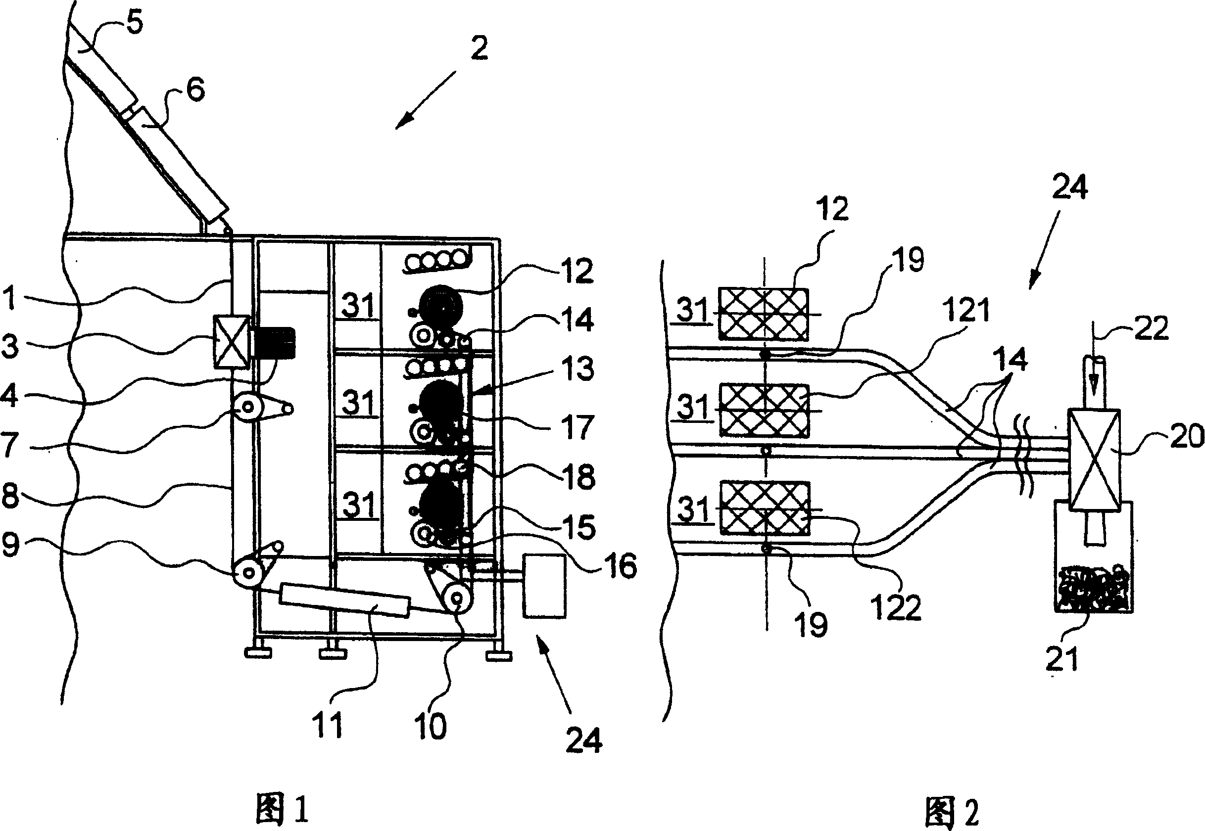
[0021] The present invention is illustrated in FIG. 1 in conjunction with the crimping process. In such a texturing process for continuous synthetic monofilaments of thermoplastic polymers, a filament 1 comprising a plurality of monofilaments is false twisted in a false twist crimper 2 by a texturing device 3 . The latter is provided to consist of a plurality of cooperating friction discs spaced apart from each other and arranged in a row overlapping each other in plan view on parallel driven spindles, the axes of which pass through the corners of an equilateral triangle. In this case the crimping device 3 is directly driven by an electric motor 4, ie one of the three main shafts is directly driven by this electric motor and the other two main shafts are driven via toothed belts. The twist in which the texturing device 3 is applied to the filament 1 is returned from the false twisting device 3 to the fixation heater 5, where the monofilament is softened thermoplastically so th...


PUM


Abstract

The invention relates to a textile machine, particularly a false twist crimping machine equipped with a thread transport system (14) for the threads (8) that continuously accrue in the event of a thread breakage or a bobbin change. The invention provides that the negative pressure in the thread transport system (14) is generated by a jet apparatus (20) supplied with a gaseous working substance. The accumulating thread waste is conveyed by the jet apparatus into a collecting receptacle (21), which also serves as a thread store while being detachably attached as an easily exchangeable thread waste bag that, for improving recycling, is made of the same polymer as the thread remnants collected therein.

Description

technical field [0001] The invention relates to a textile machine for processing continuous filaments or monofilaments, in particular a spinning, twisting or texturing machine, preferably a false twist crimping machine, comprising a waste yarn device for sucking and feeding Filaments or monofilaments that run continuously during a can change, either manually or automatically, wherein the waste filament device has a number of identical processing positions and at least one filament delivery system positioned parallel to the longitudinal front of the machine, in which system, Each of the processing stations arranged next to each other leads to a filament inlet, and the filament delivery system is connected at its downstream end to a collection container for the supplied filaments or monofilaments. Background technique [0002] Such a textile machine is known, for example, from US Pat. No. 3,381,462 A1. [0003] In US-3,381,462, many spinning processes are arranged side by sid...

Claims


Application Information

Patent Timeline
Patent Type & Authority Patents(China)
IPC IPC(8): B65H54/88D01H13/16B65H51/16
CPCD01H13/1691B65H54/88
Inventor 赖因哈德·利伯曼弗雷德·施蒂特姆马丁·施蒂勒
Owner SAURER GMBH & CO KG
Why Eureka
Try Eureka