Telescopic feed beam for rock drill and method of measuring rock drill travel

A drilling machine, telescopic technology, applied in drilling equipment and methods, drilling measurement, drill pipe, etc., can solve problems such as unreliable operation, complex detection and measurement processing skills, etc.

Inactive Publication Date: 2008-01-09
SANDVIK TAMROCK
View PDF4 Cites 3 Cited by
  • Summary
  • Abstract
  • Description
  • Claims
  • Application Information

AI Technical Summary

Problems solved by technology

The detection of such systems and the measurement processing techniques are complex and do not operate reliably

Method used


Image

  • Telescopic feed beam for rock drill and method of measuring rock drill travel
  • Telescopic feed beam for rock drill and method of measuring rock drill travel
  • Telescopic feed beam for rock drill and method of measuring rock drill travel

Examples


Embodiment Construction

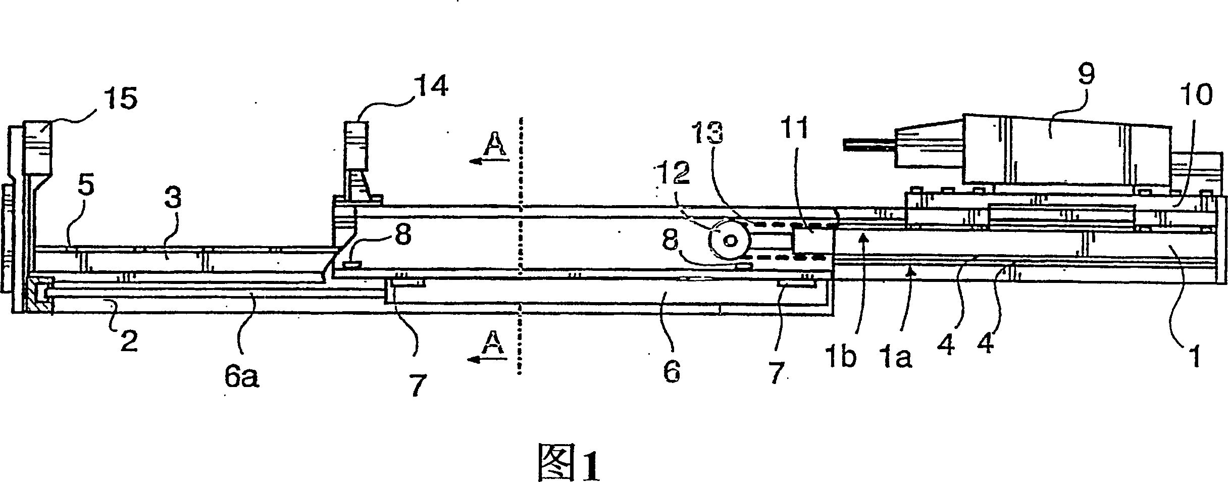
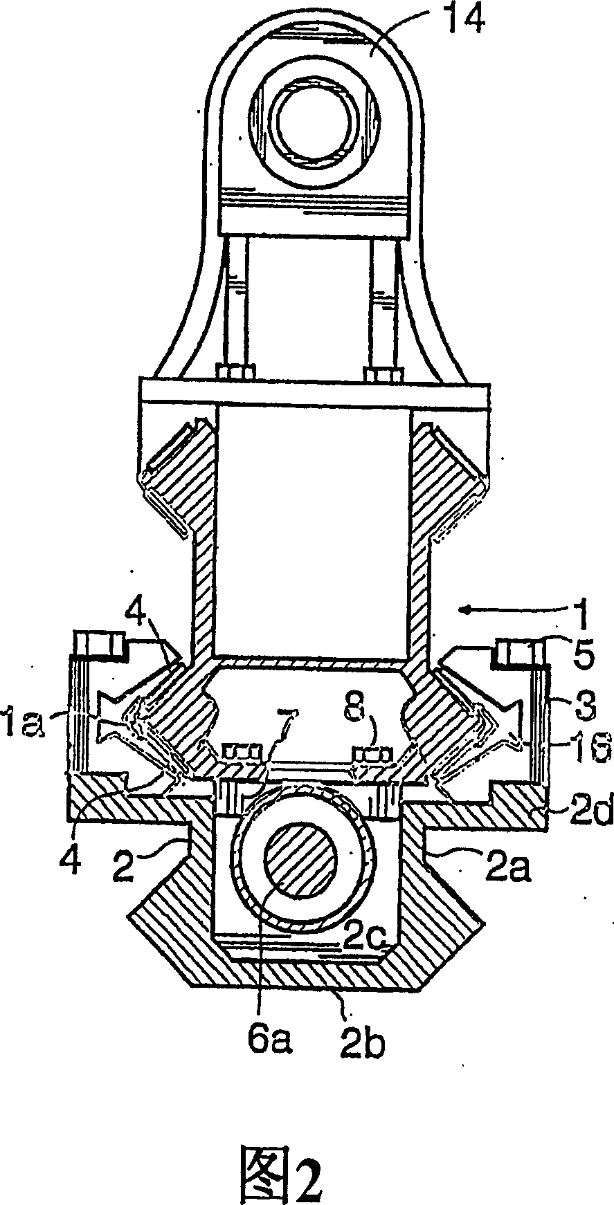
[0014] FIG. 1 shows a telescopic feed rod comprising an upper rod 1 and a lower rod 2 . The upper bar 1 and the lower bar 2 are mutually slidably installed along the longitudinal direction thereof by means of a slide rail 1a under the upper bar 1 and a slider 3 connected to the lower bar 2 . The upper rod 1 is manufactured from, for example, an aluminum alloy by extrusion, and its sliding surface is preferably formed at the same time. The sliding track has a sliding surface 4 for the slider, which is usually a steel band in an aluminum rod or the like. While the slide 3 is again most preferably made of aluminum profiles, slides are connected to the slide 3 in the manner shown in FIG. 2 , the slides being in contact with the sliding surface 4 . The slider 3 is connected to the lower rod 2 with a bolt 5 . At the front end of the lower bar 2, preferably the slider extends substantially over the entire length of the upper bar 1, the sliding means thus supporting the upper bar ov...


PUM


Abstract

The invention relates to a telescopic feed beam for a rock drill and to a method of measuring a travel length. The pressure surface of a piston (11b) in a feed cylinder (11) of the feed beam is twice as large as the pressure surface of a piston (6b) in a feed extension cylinder (6). Furthermore, the feed beam comprises a flow indicator (19) for measuring the volume flow rate of hydraulic fluid fed and / or discharged, and thereby the travel length.

Description

technical field [0001] The present invention relates to a telescopic feed rod for a rock drilling machine, comprising a lower rod intended to be connected to a boom of rock drilling equipment, and an upper rod mounted slidably relative to the lower rod along its longitudinal direction, and connected to the an upper rod and a lower rod and acting therebetween a feed extension cylinder for moving the upper rod relative to the lower rod, a feed cylinder for moving the rock drilling machine relative to the upper rod, such as a chain or A flexible transmission element of a wire rope mounted to be driven by the feed cylinder and connected to the upper rod and the rock drilling machine or its support respectively such that the rock drilling machine is relative to the feed cylinder or its rod The stroke length of is shifted double the stroke length, so the feed extension cylinder and the cylinder space in the feed cylinder to which hydraulic fluid is fed via the feed conduit during th...

Claims


Application Information

Patent Timeline
Patent Type & Authority Patents(China)
IPC IPC(8): E21B15/04E21B19/086E21B45/00E21B7/02
CPCE21B45/00E21B7/025E21B7/022E21B19/086
Inventor 尤哈·皮波宁
Owner SANDVIK TAMROCK
Why Eureka
Try Eureka