
Return pipe heat exchanger

A heat exchanger and return pipe technology, applied in the field of return pipe heat exchangers, can solve the problems of only vertical installation, inconvenient use, and large dimensions, and achieve the effects of convenient layout, high reliability, and low cost

Inactive Publication Date: 2008-01-16
彭建华
View PDF6 Cites 0 Cited by
  • Summary
  • Abstract
  • Description
  • Claims
  • Application Information

AI Technical Summary

Problems solved by technology

The plate heat exchanger is compact in structure and high in efficiency, but it is expensive and has many faults, and generally can only be installed vertically, which is not suitable for use in some occasions with special requirements for height; although the casing heat exchanger is cheap, its Large form factor and inconvenient to use

Method used


Image

  • Return pipe heat exchanger
  • Return pipe heat exchanger
  • Return pipe heat exchanger

Examples


Embodiment 1

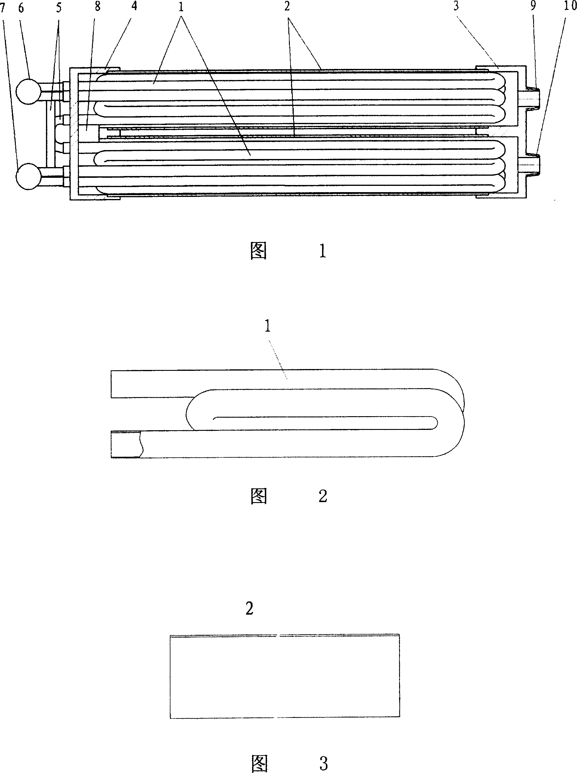
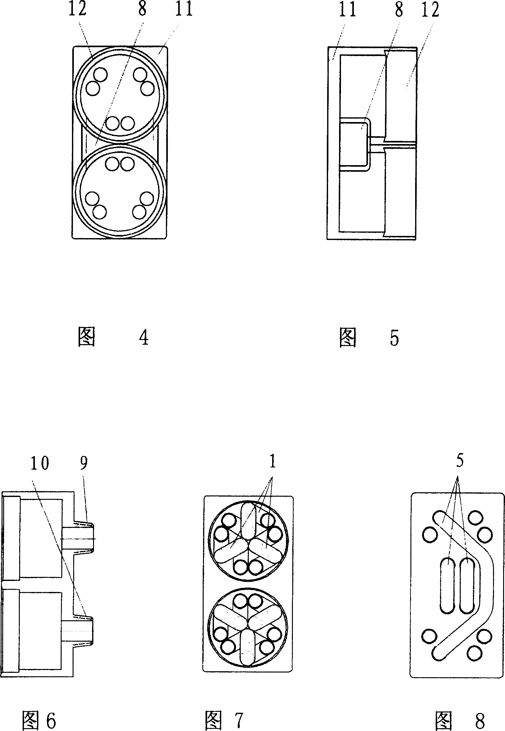
[0032] Example 1: double-tube return pipe heat exchanger

[0033] Combining Figure 1-Figure 3:

[0034] The present embodiment is provided with two cylinders 2, and the cylinders are elongated metal cylinders, and each cylinder 2 has three return pipes 1 that circle back and forth twice. The return pipe 1 in this embodiment is integrally bent. The two cylinders 2 are inserted into the grooves of the two sleeves 12 of the left end cover 4 and the right end cover 3 to form the shell of the heat exchanger. There are inlets 10 and outlets 9 on the end covers, and a total of 12 tube heads for return pipes. Pass through the cover plate 11 of the left end cover 4. The adjacent head and tail pipe heads of the same group of return pipes are connected through the connecting elbow 5, and the inlet and outlet ends of each group of return pipes are respectively connected through the upper distributor 6 and the lower distributor 7 to form a main pipe, and there are communication holes bet...

Embodiment 2

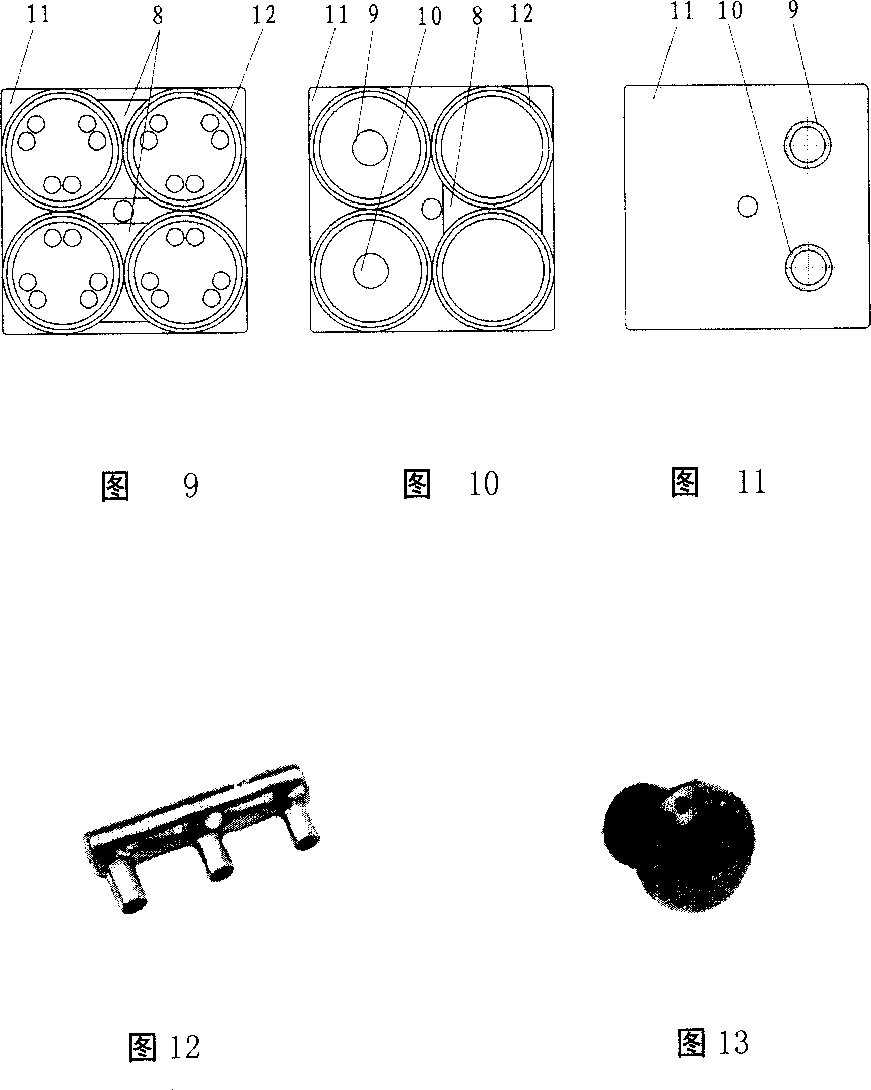
[0038] Example 2: 4 tubes (2×2 matrix arrangement) return tube heat exchanger

[0039] Combined with Figure 9-Figure 11:

[0040] The difference from Example 1 is that 6 groups of return pipes 1 are respectively placed in 4 cylinders 2 to form a (2×2 matrix arrangement), and the number of sockets 12 is the same as the number of cylinders, which are 4.


PUM


Abstract

The present invention relates to a return pipe heat exchanger which can be used as condenser and evaporator and is applicable to medium / small water cooling air conditioner, water source heat pump, domestic central air conditioner and air source heat pump water heater, etc. Said invention includes the external shell of said heat exchanger and heat-exchanging pipe-return pipe mounted in the external shell. Said invention also provides their concrete structure and its working principle.

Description

technical field [0001] The invention relates to a return pipe heat exchanger suitable for use as a condenser and an evaporator in small and medium-sized water-cooled air conditioners, water source heat pumps, domestic central air conditioners, and air source heat pump water heaters. Background technique [0002] At present, there are only three basic types of heat exchangers that can be used as heat exchange devices between liquid phase or gas-liquid two-phase fluid: plate heat exchanger, shell-and-tube heat exchanger and casing heat exchanger. The return pipe in the shell-and-tube heat exchanger is an ordinary straight pipe or U-shaped pipe, and the heat exchanger is equipped with water-dividing ribs; it is only suitable for occasions with large heat flow, and the heat exchanger suitable for small and medium heat flow is only Tube and tube heat exchangers and plate heat exchangers. The plate heat exchanger is compact in structure and high in efficiency, but it is expensive...

Claims


Application Information

Patent Timeline
Patent Type & Authority Patents(China)
IPC IPC(8): F28D7/00
Inventor 彭建华
Owner 彭建华
Learn More